TP de conception d'un système de gestion des feux d’un carrefour⚓
VHDL Cheat⚓
https://memo-vhdl.gitlab-pages.imt-atlantique.fr/
Dépôt Gitlab associé⚓
Un dépôt gitlab tp-carrefour-etudiant est disponible dans votre espace gitlab sur https://gitlab-df.imt-atlantique.fr, dans le groupe correspondant à l'enseignement suivit.
Pour le manipuler (clone, add, commit, push, pull), veuillez vous référer à la page Git et Gitlab .
Objectif du TP⚓
Ce TP a pour objectif de vous initier à la conception des circuits intégrés numériques. Il vise l’intégration d’un système de gestion de feux routiers tricolores entre une route prioritaire et un chemin.
Partant de la description du fonctionnement désiré du système, vous concevrez une architecture sur papier, la décrirez en VHDL (langage dédié à l’électronique numérique), effectuerez la simulation et la synthèse logique du système, et enfin le testerez sur circuit reconfigurable de type Field-Programmable Gate Array (FPGA).
Un squelette du projet vous sera fournit. Il contient des fichiers sources VHDL dont certains sont incomplets, il vous faudra les compléter.
Les feux tricolores⚓
Il s’agit d’un système de gestion d’un carrefour entre une route et un chemin utilisant des feux tricolores comme présenté sur la figure suivante. Par défaut, la route est au vert.
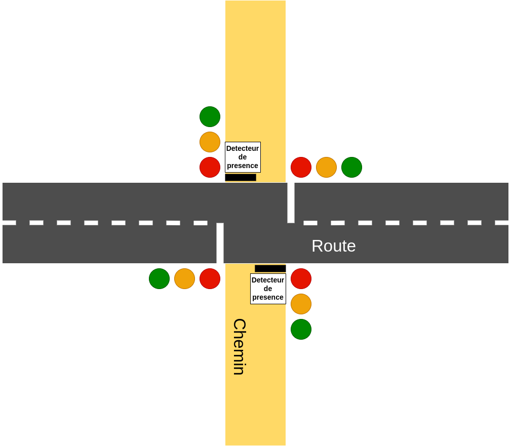
Si un véhicule est présent sur le chemin, un capteur détecte sa présence et l’alternance des feux se met en place :
- La route est au vert
- Un véhicule est présent sur le chemin
- La route passe à l’orange puis au rouge après être restée un temps minimum au vert
- Les deux feux sont au rouge
- Le chemin passe au vert, à l’orange puis au rouge ;
- Les deux feux sont au rouge ;
- La route revient au vert pendant un temps minimum, même si un autre véhicule est déjà présent sur le chemin.
À l’allumage du dispositif, les deux feux doivent être au rouge (ce qui s’obtient aussi par appui sur le bouton reset). Les temps à respecter sont les suivants :
- durée minimum où la route est verte : TRV = 9s,
- durée où la route ou le chemin sont à l’orange : TROCO = 3s,
- durée où le chemin est vert : TCV = 7s,
- durée où les deux feux sont rouges : Tsecu = 2s.
Pour chacune de ces temporisations, un compte à rebours indique aux automobilistes le temps restant avant le passage des feux d’un état à l’autre. Ce compte à rebours est affiché sur un afficheur 7 segments.
Description de l’architecture du circuit⚓
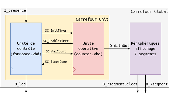
Le circuit de gestion des feux tricolores est composé de deux modules principaux : une unité opérative et une unité de contrôle, laquelle est décrite par un automate à états finis. Ces deux modules combinés implémentent l’algorithme précédemment décrit. Chaque opération correspond à l’exécution d’une instruction donnée par l’automate à la partie opérative. De son côté, la partie opérative envoie des informations d’état à l’automate de contrôle pour indiquer l’état d’avancement de l’opération. Le VHDL du circuit de gestion des feux est fourni incomplet.
En plus de ces deux modules, un troisième est chargé de la communication avec les périphériques, à savoir l’afficheur de compte à rebours.
L’architecture globale est représentée en figure suivante :
Partie Opérative⚓
L’unité opérative est ici constituée de de décompteurs de temps se basant sur la fréquence d’horloge de la carte !!!!!!!!!!!!!!!!!!!!!!! LIEN VERS DOC NEXYS à 100 MHz. La figure suivante montre son architecture.
Un premier compteur (SR_counterPulse) permet de générer une impulsion (SC_secondPulse) toutes les secondes, c’est à dire un signal qui passe à ’1’ pendant une période d’horloge une fois par seconde et reste à ’0’ sinon. Un deuxième compteur (SR_counterSecond) utilise cette impulsion ainsi qu’une valeur initiale de décomptage (I_maxCount) pour décompter les secondes. On retrouve en entrée, outre l’horloge I_clk et le reset I_rst (utilisé de manière asynchrone), un signal d’initialisation I_init (utilisé de manière synchrone), une valeur d’initialisation I_maxCount, et un signal d’autorisation de fonctionnement I_enable. Étant donné qu’une seconde représente 100 000 000 cycles d’horloge, cette structure à deux compteurs offre la possibilité de modifier facilement le nombre de secondes à décompter pour faciliter sa simulation
Partie Contrôle⚓
La partie contrôle est chargée du pilotage des compteurs et du bon déroulement de l’algorithme. Pour l’implémentation du contrôle, nous utiliserons une machine à états finis (FSM pour Finite State Machine). Il y a deux types de FSM possibles : Moore et Mealy.
Avec une FSM de Moore, les sorties ne dépendent que de l’état dans lequel le système se trouve (SR_presentState). La conception est donc plus simple. En contrepartie, la FSM réagit toujours à une modification sur une entrée avec un cycle de retard.
Avec une FSM de Mealy, les sorties dépendent de l’état dans lequel le système se trouve, mais aussi des entrées (si besoin). Une telle FSM permet plus de flexibilité et une plus grande réactivité vis-à-vis de la gestion des sorties, mais sa conception est un peu plus délicate.
Ici nous allons nous concentrer sur la machine de Moore (sauf instruction contraire de l’enseignant).
Travaux de conception numérique⚓
Travail préparatoire⚓
Question
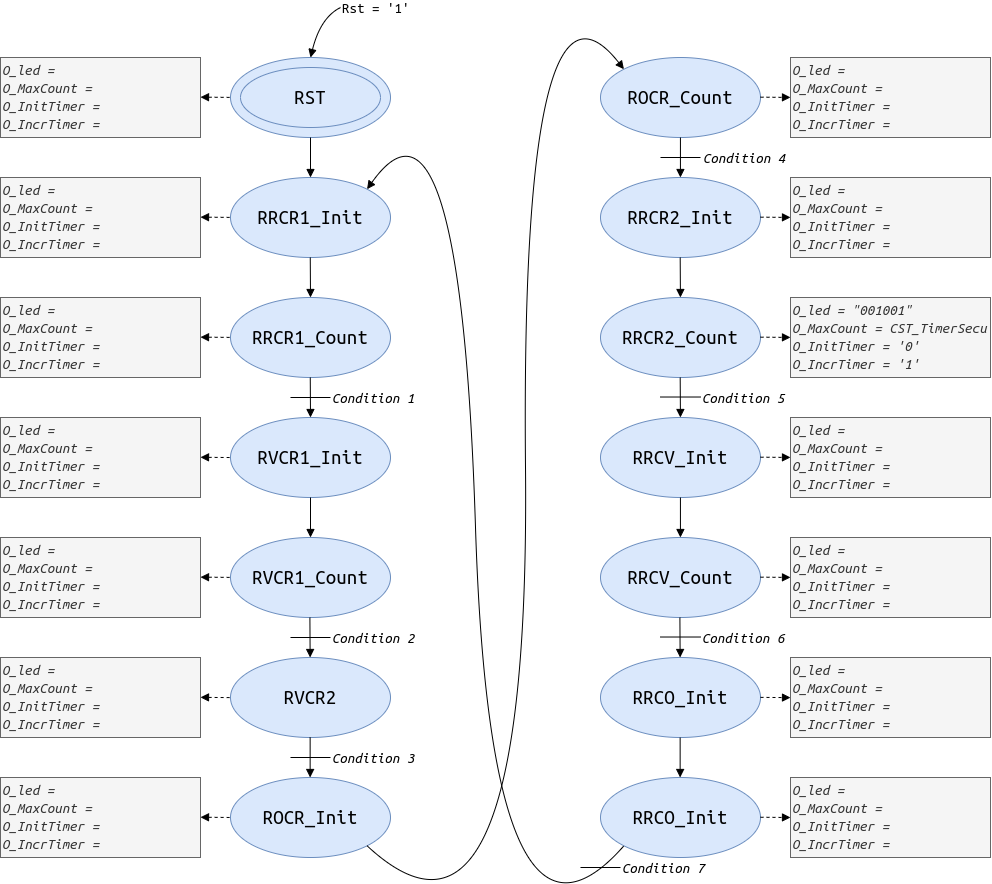
Il faut compléter le diagramme de la FSM de Moore sur la base du fichier doc/img/FSM-moore.drawio, modifiable via l'application Draw.io disponible en ligne : https://app.diagrams.net/. Ou celle de Mealy si explicitement demandé par l’enseignant, ou si le temps le permet.
Pour cela, il faut comprendre l’interaction entre le contrôle et la partie opérative. Les états sont déjà proposés, à vous de fournir les conditions de transition entre les états (les différentes expressions de conditions Ci sur le diagramme) et les valeurs des instructions à déclencher pour chaque état, sur la base de l’exemple fourni pour l’état RRCR2.
Travail en salle⚓
Vous utiliserez le logiciel Vivado 2019.2 pour décrire et synthétiser votre circuit sur la base des fichiers disponible dans votre dépôt git tp-carrefour-etudiant-login sur https://gitlab.imt-atlantique.fr.
Pour lancer vivado sur une machine campux de TP, ouvrez un terminal et lancer les commandes suivantes :
1 2 | |
- Le module de compteurs (
counter.vhd), qu’il faudra tester avec le test bench associé - La FSM de Moore (
fsmMoore.vhd) - Le module de carrefour, qui est l’assemblage de la FSM et du module de compteur (
carrefourUnit.vhd) qu’il faudra tester avec test bench associé - Le module de gestion de l’affichage 7 segments (
decimalTo7segment.vhd)
Les fichiers de contraintes, de test et d’intégration restant sont fournis.
Le circuit à configurer est un FPGA Xilinx Artix-7 100T (XC7A100TCSG324-1) qui est embarqué sur la carte Digilent Nexys 4 comprenant, outre le FPGA, de nombreux périphériques.
La documentation de la carte est disponible dans votre dépôt git (doc/nexys4_rm.pdf). Cette documentation vous sera utile pour comprendre l’usage des périphériques.
Références⚓
- Syntaxe VHDL : https://memo-vhdl.gitlab-pages.imt-atlantique.fr/
lab of traffic light system design⚓
VHDL Cheat⚓
https://memo-vhdl.gitlab-pages.imt-atlantique.fr/
Associated Gitlab repository⚓
A gitlab repository tp-carrefour-etudiant is available in your gitlab space on https://gitlab-df.imt-atlantique.fr, in the group corresponding to the course you are following.
To manipulate it (clone, add, commit, push, pull), please refer to the page Git and Gitlab.
Objective of the lab⚓
This lab aims to introduce you to the design of digital integrated circuits. It aims to integrate a traffic light management system between a priority road and a path.
Starting from the description of the desired operation of the system, you will design an architecture on paper, describe it in VHDL (a language dedicated to digital electronics), simulate and synthesize the system, and finally test it on a reconfigurable circuit of the Field-Programmable Gate Array (FPGA) type.
A skeleton of the project will be provided to you. It contains VHDL source files, some of which are incomplete, and you will need to complete them.
The traffic lights⚓
This is a system for managing a crossroads between a road and a path using traffic lights as shown in the following figure. By default, the road is green.
If a vehicle is present on the path, a sensor detects its presence and the alternation of the lights is put in place:
- The road is green
- A vehicle is present on the path
- The road turns orange and then red after remaining a minimum time in green
- Both lights are red
- The path turns green, then orange and then red;
- Both lights are red;
- The road turns green for a minimum time, even if another vehicle is already present on the path.
At the start of the device, both lights must be red (which is also obtained by pressing the reset button). The times to be respected are as follows:
- minimum duration where the road is green: TRV = 9s,
- duration where the road or the path are orange: TROCO = 3s,
- duration where the path is green: TCV = 7s,
- duration where both lights are red: Tsecu = 2s.
For each of these timings, a countdown indicates to motorists the time remaining before the lights change from one state to another. This countdown is displayed on a 7-segment display.
Description of the circuit architecture⚓
The traffic light management circuit consists of two main modules: an operative unit and a control unit, which is described by a finite state automaton. These two combined modules implement the algorithm previously described. Each operation corresponds to the execution of an instruction given by the automaton to the operative part. For its part, the operative part sends state information to the control automaton to indicate the progress of the operation. The VHDL of the traffic management circuit is incomplete.
In addition to these two modules, a third one is responsible for communication with peripherals, namely the countdown display.
The global architecture is represented in the following figure:
Operative Part⚓
The operative unit here consists of time counters based on the clock frequency of the board at 100 MHz. The following figure shows its architecture.
A first counter (SR_counterPulse) generates a pulse (SC_secondPulse) every second, i.e. a signal that goes to '1' for one clock period once per second and remains at '0' otherwise. A second counter (SR_counterSecond) uses this pulse as well as an initial counting value (I_maxCount) to count the seconds. In addition to the clock I_clk and the reset I_rst (used asynchronously), an initialization signal I_init (used synchronously), an initialization value I_maxCount, and an enable signal I_enable are input. Since one second represents 100,000,000 clock cycles, this two-counter structure offers the possibility to easily modify the number of seconds to be counted to facilitate its simulation.
Control Part⚓
The control part is responsible for controlling the counters and the smooth running of the algorithm. For the control implementation, we will use a finite state machine (FSM). There are two types of possible FSMs: Moore and Mealy.
With a Moore FSM, the outputs depend only on the state in which the system is (SR_presentState). The design is therefore simpler. On the other hand, the FSM always reacts to a change in an input with a one-cycle delay.
With a Mealy FSM, the outputs depend on the state in which the system is, but also on the inputs (if necessary). Such an FSM allows more flexibility and greater reactivity to the management of the outputs, but its design is a little more delicate.
Here we will focus on the Moore machine (unless explicitly requested by the teacher).
Digital design work⚓
Preparatory work⚓
Question
You must complete the diagram of the Moore FSM based on the file doc/img/FSM-moore.drawio, which can be modified via the Draw.io application available online: https://app.diagrams.net/. Or that of Mealy if explicitly requested by the teacher, or if time permits.
To do this, you need to understand the interaction between control and operative parts. The states are already proposed, you have to provide the transition conditions between the states (the different conditions Ci on the diagram) and the values of the instructions to trigger for each state, based on the example provided for the state RRCR2.
Work in the classroom⚓
You will use the Vivado 2019.2 software to describe and synthesize your circuit based on the files available in your git repository tp-carrefour-etudiant-*login* on https://gitlab.imt-atlantique.fr.
To launch vivado on a TP campux machine, open a terminal and run the following commands:
1 2 3 | |
The launch of the tool can be quite long. During the sessions, you will complete the provided code of the following parts:
- The counter module (
counter.vhd), which will need to be tested with the associated test bench - The Moore FSM (
fsmMoore.vhd) - The carrefour module, which is the assembly of the FSM and the counter module (
carrefourUnit.vhd) which will need to be tested with the associated test bench - The 7-segment display management module (
decimalTo7segment.vhd)
The constraint, test and integration files remaining are provided.
The circuit to be configured is a Xilinx Artix-7 100T FPGA (XC7A100TCSG324-1) which is embedded on the Digilent Nexys 4 board including, in addition to the FPGA, many peripherals.
The documentation of the board is available in your git repository (doc/nexys4_rm.pdf). This documentation will be useful to understand the use of the peripherals.
References⚓
- VHDL syntax: https://memo-vhdl.gitlab-pages.imt-atlantique.fr/