SEIML SW: Introduction to Linux on the Zedboard⚓
Hardware setup⚓
- Download the lab material
- Move it to
/users/local/seiml_sw_lab
Warning
Working in /users/local/ is important as it is a local disk, which will significantly speed up each step of the lab.
First of all, we will create a vivado project to generate the hardware.
1 2 | |
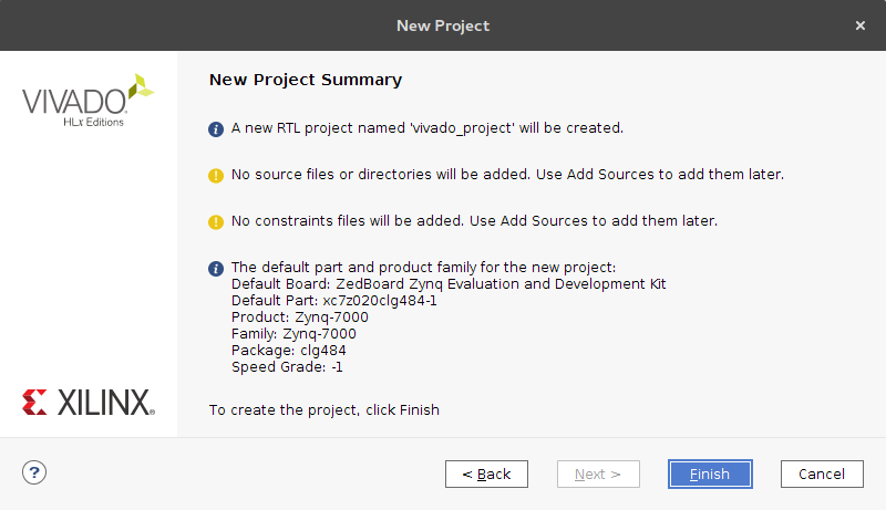
- Create a new Vivado project
- Project name:
vivado_project - Location:
/users/local/seiml_sw_lab - Project type: RTL project
- Skip
Add sourcesandAdd constraints - Click on
Boardsand selectZedboard
- Project name:
- Create block design
- Design name:
system - Directory: local to project
- Design name:
- Add IP (
+button): ZYNQ7 Processing System - Add 2 IP: AXI GPIO
- Add IP: Chenillard
- Go to IP Catalog
- Right click and add repository:
/users/local/seiml_sw_lab/resources/ip_repo_chen - Add chenillard in the block diagram
- Regenerate layout
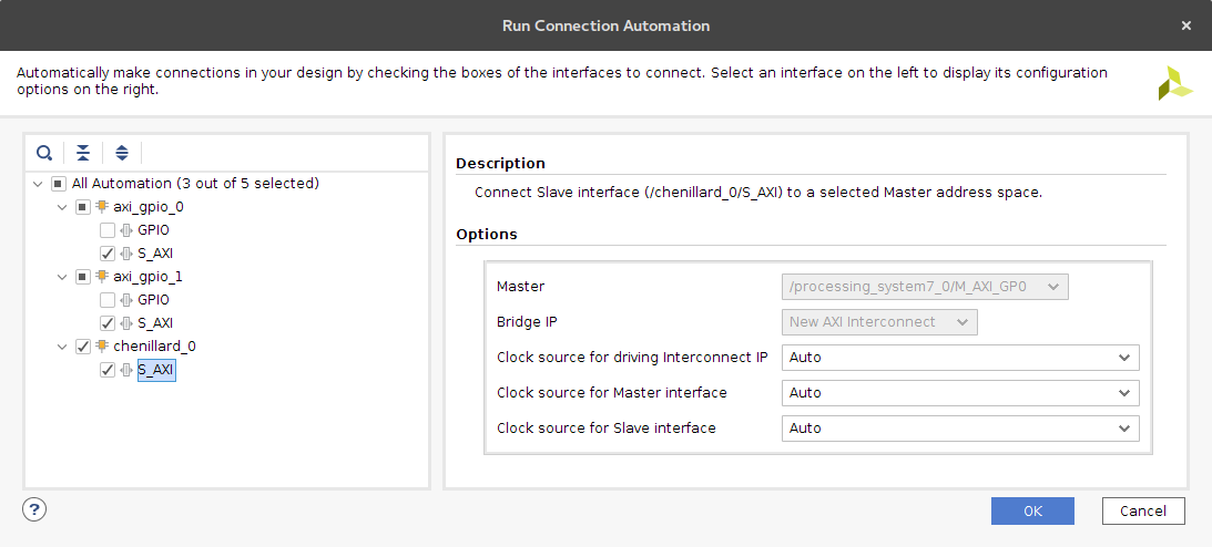
- Click the Run Block Automation button
- Click the Run Connection Automation button
- Only connect
S_AXIinterfaces
- Rename
axi_gpio_0tobtns_gpio(In theBlock Propertiestab) - Rename
axi_gpio_1tosws_gpio(In theBlock Propertiestab) - Rerun the Connection Automation and connect the GPIO to the
sws_8bitsand thebtns_5bitsports - Enable and connect gpio interruption to the ZYNQ7 Processing System
- Double click on the
btns_gpioblock - Enable interruption
- Double click on the ZYNQ7 Processing System block
- Go to interrupts
- Enable Fabric Interrupts and
IRQ_F2Pin PL-PS Interrupts section - Go back block diagram
- Draw the connection beween
ip2intc_irptgpio output port andIRQ_F2Pinput port of the Zynq
- Double click on the
- Right click on the block diagram and Create Interface Port for leds
- Interface name:
leds_8bits - VLNV:
xilinx.com:interface:gpio_rtl:1.0
- Interface name:
- Connect the leds to the chenillard GPIO interface
- Regenerate layout
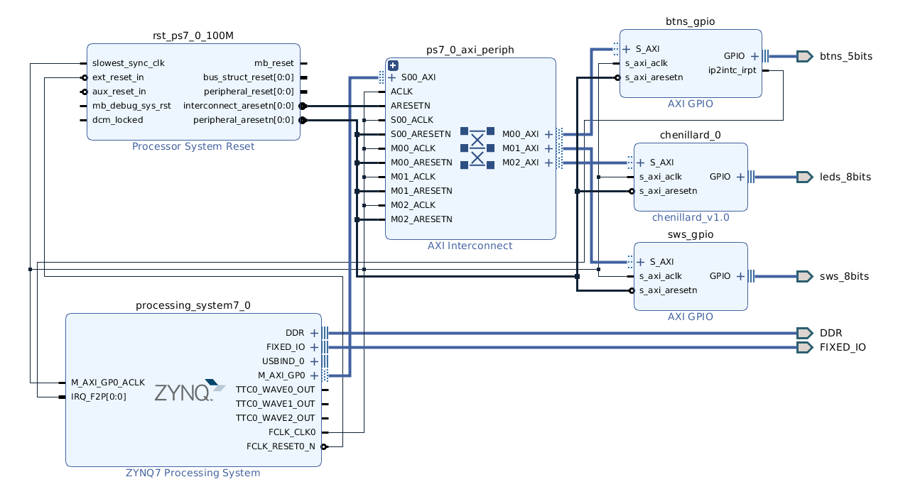
Your block design should look like this:
- Click the Generate Block Design button (under IP integrator section in the left-most tab)
- Create HDL Wrapper (in the
Sourcestab)
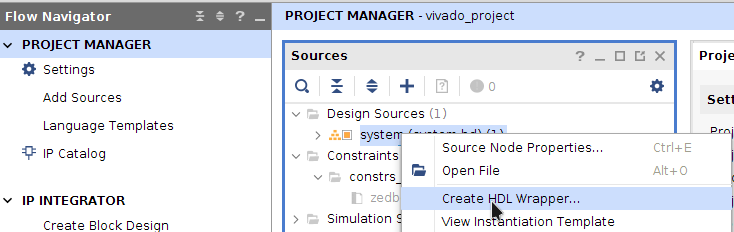
- Let Vivado manage wrapper
- Click Add source -> Add or create constraints
- Add the file
system.xdcthat can be found in/users/local/seiml_sw_lab/resources - Generate Bitstream
- Export the hardware locally (File -> Export -> Export Hardware...)
- Include the bistream
- Tools -> Launch Vitis IDE
Software setup⚓
We are now going to produce all the necessary software components:
- First Stage Boot Loader
- Boot Loader
- Linux Kernel
- Device Tree Blob
- Root File System (rootfs)
All the components that are necessary for boot will be stored on the QSPI flash, with the following memory layout:
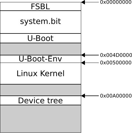
The root file system will be stored on an NFS server on the host machine. Therefore we will need to configure U-Boot to load the rootfs on the nfs. But first things first, the First Stage Boot Loader:
First Stage Boot Loarder⚓
We will generate the FSBL using Xilinx SDK
- Create a new Application project (File -> New -> Application project)
- Create a new platform from hardware (select your own .xsa)
- Click Next
- Insert Application project name:
zynq_fsbl - Click Next
- Domain (nothing to change here)
- Click Next
- Choose Zynq FSBL template
- Click Finish
- Project -> Build Project
The build will create the zynq_fsbl.elf executable in the Debug folder, that will be used later.
Note that the board support package has also been generated.
U-Boot⚓
U-Boot will be the bootloader that is proposed by Xilinx by default.
It is available online here, but we will use the version that has been packaged in the lab material folder seiml_sw_lab/u-boot-xlnx.
1 2 3 4 5 | |
Warning
For the different tools, and vivado setup, source setup.sh and SETUP MEE_VITIS20202 each time you open a terminal !
As aforementioned, we want u-boot environment to be saved at 0x004D0000 on the QSPI flash.
- In
Environment, selectEnvironment is in SPI flash, and setEnvironment offsetto0x4D0000 - Exit menuconfig and save (in
.configas proposed) - Build U-Boot
1 | |
The output product is u-boot.elf, that will be loaded in the flash.
It also produces some tools for the linux kernel build, namely mkimage that can be found in u-boot-xlnx/tools
Linux Kernel⚓
In the same way as for U-Boot, Xilinx provide the linux kernel sources adapted to their hardware targets (here).
1 2 3 4 | |
In the menus, verify that NFS File System is enabled and that RootFS can be located on NFS.
1 | |
The compiled images are located in arch/arm/boot/.
Busybox⚓
Now that the kernel has been built, we need some system utilities in order to get a complete operating system.
1 2 3 4 | |
Here you can see all the utilities that will be compiled, and the memory footprint. One could remove some features to lower the size of the OS. These utilities will populate our rootfs.
Device Tree⚓
A device tree is necessary for the kernel to be aware of the devices that need to be supported. The device tree includes information about device addresses, interruptions, compatible drivers. We need to generate the sources of this device tree for the Zedboard. Xilinx provide a device tree generator (here) and it is included in the lab material. We will use the Device Tree Compiler (dtc) provided by u-boot to compile the device tree blob that is needed at boot time.
1 2 | |
Installation⚓
Flash image⚓
In order to build the image to be written in the QSPI flash, the bootgen tool provided by Vivado will be used. First of all, let's create a folder to import all the software components that were precedently generated.
1 | |
In this directory, copy the following files:
- The FSBL (file
zynq_fsbl.elf), - the bitstream (file
system_wrapper.bit), - the bootloader (file
u-boot.elf), - the linux kernel (file
zImage), - the device tree blob (file
devicetree.dtb).
A file named boot.bif must be given to bootgen in order to place the components at the right places in memory. Create a boot.bif in /users/local/seiml_sw_lab/build_image with the following content:
1 2 3 4 5 6 7 | |
The offset values correspond to the location of the corresponding files on the Flash.
During boot, U-Boot will automatically load the kernel (uImage.bin) and the device tree blob (devicetree.dtb) in the Zynq RAM at the addresses that are specified (0x3000000 and 0x2a00000).
Now create the boot.bin image to be loaded into the QSPI Flash :
1 | |
Root FS⚓
A NFS server is set up on your machine at /srv/nfsroot.
Create a folder that will store your rootfs.
1 | |
BusyBox provides the base of this rootfs:
1 | |
Some modifications are necessary to finalize the setup
- Create following directory and files
1 2 3 | |
- Add GCC libs
1 2 | |
- Edit
etc/fstab
1 2 3 4 5 | |
- Edit
etc/passwd
1 | |
- Create and edit
etc/group
1 | |
- Edit
etc/init.d/inittab
1 2 3 4 5 6 7 8 9 10 11 | |
- Edit
etc/init.d/rcS
1 2 3 4 5 6 7 8 9 10 11 12 13 14 15 16 17 18 19 20 | |
- Set
etc/init.d/rcSpermission to 755
1 | |
Boot⚓
It's (finally) time to boot !
- Verify that the jumpers are correctly set to boot from the flash memory:
1 | |
- Connect all the necessary cables
- Ethernet cable to the host computer
- Power supply
- USB cable for PROG (J17)
- USB cable for UART (J14)
- Turn on power switch button
- Flash the board
- Move back to the
build_imagedirectory make flash
- Move back to the
- After the flash, and each time you want to reset the CPU, use:
make reset
- Open a serial terminal with putty to communicate with the board:
putty -serial /dev/ttyACM0 -sercfg 115200,8,n,1,N
- Reset the board using the
PS-RSTbutton -
Interrupt autoboot by hitting a key before the end of the countdown
-
Change the boot environment in order to boot from memory, and use our nfs server as rootfs.
1 2 3 4 5 | |
The Zedboard should now boot.
The last thing to do is to change the ownership of all the folders that are not mounted. From now on, all the files in the nfs won't be accessible from the host. We only let the home/user folder accessible from host. This is where you will work from the host computer to create your own scripts and source code, and compile them.
1 | |
You're all set !
Hands on⚓
One LED (MIO7) and two push buttons (MIO50 and MIO51) are directly connected to the PS. Therefore these are accessible directly using the /sys/class/gpio/ interface that drives the MIOs.
- Compile and test a simple "Hello World" program.
- On the host machine,
cd /srv/nfsroot/zednfsroot/home/user - Write a hello world program
- Compile with
arm-linux-gnueabihf-gcc hello.c -o hello - On the zedboard (via putty)
cd /home/user - Run the program
./hello
- On the host machine,
- Using only shell, light up the MIO7 LED
1 2 3 4 5 | |
- Develop a C program that displays the states of BTN8 and BTN9, using the same gpio interface.
Driver development⚓
/dev/mem⚓
First of all, on the host machine, move the seiml_sw_lab/resources/driver folder into /srv/nfsroot/zednfsroot.
In order to test the proper functioning of the PL part, we will perform a quick test by writing directly into the registers of our hardware design. To do this, we will use the pseudo file /dev/mem (See man 4 mem). In order to write in this pseudo file, we have to use the mmap function (See man 2 mmap).
- Develop a test program that activates chenillard mode 1 and sets the speed to 7.
/dev/chenillard⚓
We will now develop a specific driver for the chenillard. This driver will allow access to the PL for the LED chenillard (and only the LEDs at first). Information about Linux driver development is covered in detail in the book Linux Device Drivers (LDD3) here. All questions below refer to this document.
- A Makefile is provided to simplify compilation and installation. Compile, install, and test the module. Loading and unloading the module is done via the shell scripts
load.shandunload.sh. Testing will be done with theecho&catcommands first. For more information about the Linux driver structure, you can study chapter 1 and 2 of the LDD. - Complete the chenillard initialization function (
chenillard_init): memory reservation, ioremap. The TBD (To Be Done) fields are to be replaced by code. Cf chapter 9 of the LDD notably the paragraph "I/O Memory Allocation and Mapping". Also complete thechenillard_removefunction. Check that the memory area corresponding to the PL is reserved and freed in/proc/iomem. - Complete the
chenillard_i_readandchenillard_i_writefunctions: Reading/dev/chenillardshould return the current chenillard mode and speed. Use theapp.ctest program to check. Writing to the pseudo file should set the mode and speed. Modifyapp.cto test writing. See paragraph "read and write" of chapter 3 of the LDD.
/dev/btns⚓
The development of the driver for the chenillard part is now finished, we will now focus on the push buttons. The operation of the driver for the button management is slightly different because it implements a hardware interrupt.
- Based on the structure of the chase maintenance code, develop the necessary functions for button management (
axi_btns_of_probe,btns_i_open...). - Write the interrupt function
irqreturn_t axi_btns_irq_handler(). At first, this function will only perform a printk. Please refer to chapter 10 of the LDD. Modify thebtns_initfunction to take into account this new interrupt handler. Test it. Verify that the interrupt is listed in/proc/interrupts. - We choose to take the interrupt into account using a blocking read in the driver. An interruption that occurs should unblock the reading. See ''Blocking I/O`` in chapter 6 in LDD.
Important notes:
- As this interrupt is based on the AXI GPIOs, it must be activated at the BUS level. Refer to the GPIO interrupt registers in the documentation (see registers IER, GIE and ISR).
- Only IRQ_TYPE_EDGE_RISING is supported by the hardware.
Threads⚓
In the previous exercise, we noted that the integration of an external event (e.g. button push) into a program is quite constraining. It is possible to use threads to manage the blocking read.
- Develop an application to change the chenillard mode and speed using both push buttons and keyboard. To do this, use two threads. The first one will be in charge of reading the push buttons, the second one will be in charge of the keyboard. The use of threads under Linux is described on the wikipedia page: POSIX Threads
Timer⚓
Finally, you will add an AXI hardware timer in the PL part of your system, as you did in the HW labs.
Then recompile the necessary software elements.
Develop a driver like you did for the chenillard and the buttons, by setting the timer to interrupt every second.
To check the added functionality, compare the measured time with two methods, on the one hand with the gettimeofday() system call, on the other hand with your timer. This measurement will be done on an interval of ten seconds for example.