SEIML HW3: Dedicated Hardware Coprocessor⚓
Objective of the lab⚓
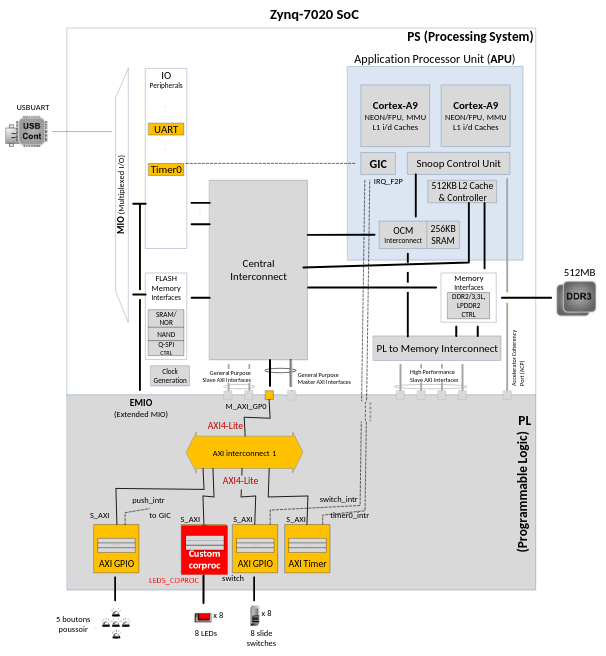
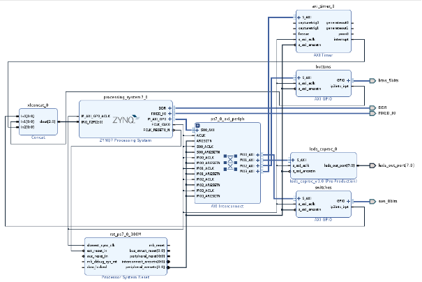
The objective of this lab is to illustrate the integration flow of dedicated hardware coprocessor and the necessary hardware/software interface. The aim is to extend the system developed in the previous lab to implement the system illustrated in Figure 1 below.
- Open a terminal and setup the Vivado-Vitis environment through the command:
1SETUP MEE_VITIS20202 - Open Vivado:
bash vivado & - Open the project of the previous lab:
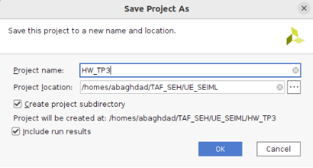
HW_TP2 - Create a copy of this project into
HW_TP3(Save Project As)
Run the Create and Package IP Wizard⚓
- Select
Tools>Create and Package New IP - In the first window, click
Next - Select
Create a new AXI4 peripheral, and clickNext - Fill in the details for the IP
- Name:
leds_coproc
- Name:
- Click
Next - Change the Name of the interface to
S_AXI - Leave the other settings as default and click
Next(Lite interface, Slave mode, Data Width: 32, Number of Registers: 4) 4 is the allowed minimum number of registers! - Select
Add IP to the repository(will be added to your project) and clickFinish.
Adapt the interface and add the coprocessor User Logic⚓
-
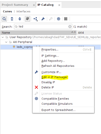
Search and select the created IP in the IP catalog, with a right-click select “Edit in IP Packager”. This will create a new Vivado Project to edit the created IP. Click OK.
-
Now, you need to examine and edit the two generated files:
leds_coproc_v1_0.vhdleds_coproc_v1_0_S_AXI.vhdThis corresponds to the HDL code for the interface(s) selected above (AXI4 lite). The top level file contains a module which implements the AXI interfacing logic, and an example design to write to and read from the number of registers specified above. This template can be used as a basis for creating custom IP. You need to add in these two files a generic parameter for the width of the leds:And declare an external output:1LED_WIDTH : integer := 8;Examine carefully the two files to see where Users can modify/add.1leds_out_port : out std_logic_vector(LED_WIDTH-1 downto 0);
-
You need now to examine and add the VHDL code of the coprocessor provided in
leds_coproc_user_logic.vhdon Moodle. This code should be declared and instantiated inleds_coproc_v1_0_S_AXI.vhdfile! -
Add the declaration of the component before the beginning of the description of the architecture:
And add the instantiation of it near the end:1 2 3 4 5 6 7 8 9 10 11 12 13 14 15 16
component leds_coproc_user_logic generic ( LED_WIDTH : in integer := 8; ); port ( S_AXI_ACLK : in std_logic; S_AXI_ARESETN : in std_logic; slv_reg_wren : in std_logic; axi_awaddr : in std_logic_vector(1 downto 0); S_AXI_WDATA : in std_logic_vector(31 downto 0); slv_reg0 : in std_logic_vector(31 downto 0); slv_reg1 : in std_logic_vector(31 downto 0); slv_reg2 : in std_logic_vector(31 downto 0); leds_out_port : out std_logic_vector(LED_WIDTH-1 downto 0) ); end component;1 2 3 4 5 6 7 8 9 10 11 12 13 14 15 16 17 18 19 20 21
-- Add user logic here -- Instantiation of Axi Bus Interface S_AXI leds_coproc_user_logic_inst : leds_coproc_user_logic generic map ( LED_WIDTH => 8 ) port map ( S_AXI_ACLK => S_AXI_ACLK, S_AXI_ARESETN => S_AXI_ARESETN, slv_reg_wren => slv_reg_wren, axi_awaddr => axi_awaddr(C_S_AXI_ADDR_WIDTH-1 downto ADDR_LSB), S_AXI_WDATA => S_AXI_WDATA, slv_reg0 => slv_reg0, slv_reg1 => slv_reg1, slv_reg2 => slv_reg2, leds_out_port => leds_out_port ); -- User logic ends -
After saving the files, click on the Add Sources in the Flow Navigator pane, and add the provided source code of the coprocessor:
leds_coproc_user_logic.vhd - Click Run Synthesis and Save if prompted. This is to check the design synthesizes correctly. If this was your own design, you would simulate it and verify functionality before proceeding.
- Check the Messages tab for any errors and correct if necessary before moving to the next step. When Synthesis completes successfully, click Cancel.
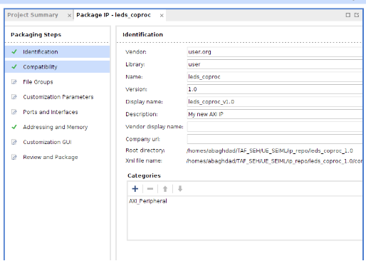
- Open the Package IP as shown above and go over the different tabs to verify and configure them, then to regenerate the IP in order to take the changes made.
- Click on Customization Parameters and Merge changes from Customization Parameters Wizard. Notice that the Ports and Interfaces view now shows the user created leds_out_port port
- Select Customization Parameters, expand Hidden Parameters, right-click on LED_WIDTH, and select Import IP Parameters… and click OK.
- Select Customization GUI and notice that the Led Width is visible.
- Select Review and Package, and notice the path where the IP will be created. Click Re-Package IP to take the changes into consideration.
- Close the Vivado coprocessor project and go back to the initial Vivado project.
Add the coprocessor to your design⚓
- Use the same flow as in previous TPs to remove the current GPIO of LEDs and add the new created IP to your system.
- The hardware system should look like this:
- Run Design Validation (Tools -> Validate Design) and verify there are no errors.
- IMPORTANT: is appears that after a “Project Save as”, the top-level system_wrapper.vhd is no more updated automatically when changes are made to in the Block design (a bug in 2020.2 version). This is an issue when the changes are related to external ports which is the case here! So, you need to remove the system_wrapper.vhd from the project (delete it) and create a new wrapper by right-clicking on system.bd, and select Create HDL Wrapper… Leave the Let Vivado manage wrapper and auto-update option selected, and click OK.
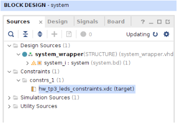
- Add the constraint file provided (on Moodle) for the leds and verify it.
To add it, in Sources tab, use Add Sources -> Add or create constraints.
Then you need to set it as Target Constraint File (if other constraint files exist already).
 Note that in the previous labs the assignment of FPGA pins has been done automatically by Vivado as the LEDs are defined already in the ZedBoard files. However this is not the case for the new custom dedicated coprocessor!
 - In the Flow Navigator, click Run Synthesis.
Generate Bitstream, Export to Vitis and Create a software application to test the coproc⚓
- Generate the Bitstream.
- Export the hardware (File > Export > Export Hardware), include the bitstream and choose a name for the Xilinx Shell Architecture (XSA) file, like
hwtp3_wrapper. - Start Vitis by clicking Tools > Launch Vitis IDE. Remember: when you copied the project from HW_TP2 through “save as”, only the hardware design has been copied. Therefore, you can create at this step a new workspace for Vitis related to HW_TP3.
- Develop a new software application to illustrate the operation of the integrated coprocessor:
- Use the Timer (AXI_Timer in the PL), in interrupt mode. For example, to change the LED scrolling configuration every 4 seconds.
- Use the push buttons to speed up or slow down the LEDs scrolling speed.
You can use the API functions generated by Vivado for your coprocessor in leds_coproc.h:
1 2 3 4 5 | |