TP de conception d’un processeur de son⚓
VHDL Cheat⚓
https://memo-vhdl.gitlab-pages.imt-atlantique.fr/
Dépôt Gitlab associé⚓
Un dépôt gitlab tp-filtre-etudiant est normalement disponible dans votre espace gitlab sur https://gitlab-df.imt-atlantique.fr, dans le groupe correspondant à l'enseignement suivi.
Pour le manipuler (clone, add, commit, push, pull), veuillez vous référer à la page Git et Gitlab .
Si aucune création de dépôt n'est prévue pour votre enseignement, ou si vous voulez faire ce TP librement. Le dépôt de référence est ici : https://gitlab.imt-atlantique.fr/tp-vhdl/tp-filtre-etudiant
Objectif⚓
Ce TP propose une brève initiation à la conception de circuits intégrés numériques, en découvrant l’intégration d’une fonction essentielle dans le traitement de l’information et du signal : le filtrage. Partant d’un algorithme, vous devrez décrire une architecture en VHDL (langage dédié à l’électronique), effectuer sa synthèse et enfin tester cette architecture sur circuit reconfigurable de type Field-Programmable Gate Array (FPGA).
Note
Un code VHDL vous sera partiellement proposé, il vous faudra le compléter, sur la base du travail préparatoire qui vous est demandé.
Info
Pour votre information, sachez que les FPGA tiennent une place essentielle au sein des systèmes audiophiles haut de gamme (tels ceux de PSaudio) depuis plusieurs années et commencent à percer dans les produits « grand-public » avec les formats haute-résolution dont les FPGA savent tirer pleinement partie (comme au sein du Chord Mojo pour les balladeurs audiophiles).
Filtrage de signaux sonores⚓
Description de l’algorithme⚓
Un signal sonore s(t), continu en temps et en valeur, est communément échantillonné à 44,1kHz pour les applications musicales (22kHz pour la radio et 8kHz pour le téléphone) puis numérisé sur un nombre restreint de bits (8, 16 ou 24 bits sont communs). Le résultat est alors une séquence d’échantillons S(k). Ce signal peut être filtré pour de nombreuses raisons, comme pour accentuer certains effets ou corriger des imperfections par exemple. Dans ce TP, nous ne considérerons que des filtres linéaires simples à Réponse Impulsionnelle Finie (RIF). Appliquer un tel filtre h sur un signal continu s(t), supposerait que nous disposions d’un circuit analogique de filtrage capable de réaliser la convolution h ∗ s(t). Pour la réaliser sur un signal numérique, nous allons dérouler un calcul équivalent, remplaçant l’intégrale de la convolution par une somme discrète sur une profondeur finie de N échantillons et en conservant la multiplication de la convolution. Ainsi, pour tout échantillon S(k), l’échantillon filtré S′(k) est tel que :
Cette équation peut se traduire sous forme d’algorithme appliqué à tout échantillon S(k) sur l’entrée S_IN qui est considéré comme valide par le filtre quand un signal binaire de contrôle VALID passe de 0 à 1 :
1 2 3 4 5 6 7 8 9 10 11 12 13 14 15 16 17 18 19 20 21 22 23 24 25 26 27 | |
Le signal de sortie S_OUT change d’état à la même fréquence que S_IN.
Description de l’architecture de circuit⚓
Le processeur numérique de filtrage peut être décrit comme composé de deux modules, une unité opérative et une unité de contrôle décrite par un automate à états finis, fourni incomplet. Ces deux modules combinés reflètent l’algorithme précédemment décrit. Chaque opération correspond à l’exécution d’une instruction donnée par l’automate à la partie opérative (loadShift, initAddress, incAddress, initSum, loadSum, loadOutput). La partie opérative peut envoyer des informations d’état à l’automate de contrôle, comme ici un bit processingDone indiquant que l’on traite le dernier produit S(k − i) × H(i).
Schéma de l'architecture de l'unité de filtrage :⚓
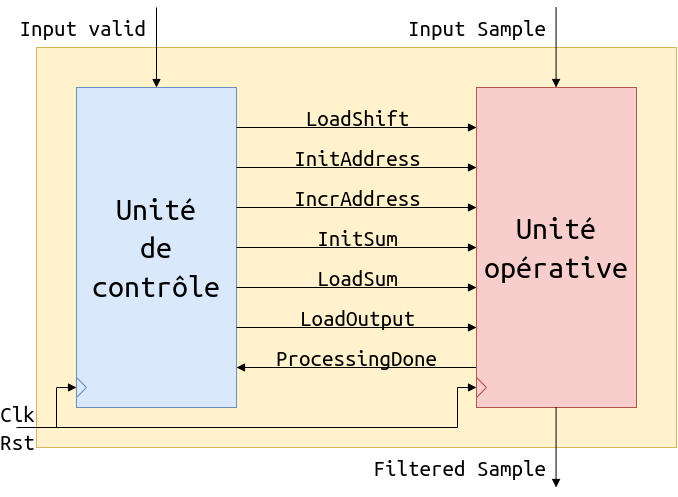
Note
Correspond au fichier VHDL FirUnit.vhd à remplir pour compléter le projet
Diagramme de la machine à état finie :⚓
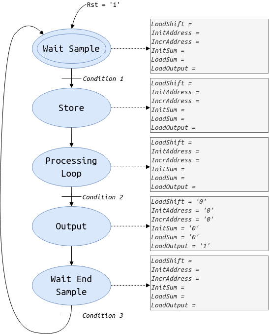
Note
Ce diagramme est à compléter pour pouvoir ensuite compléter le fichier VHDL controlUnit.vhd. Pour cela, vous pouvez utiliser le fichier FSM.drawio disponible dans le dépôt git, il s'agit du fichier docs/img/FSM.drawio avec l'outil https://app.diagrams.net/. Il faut ensuite mettre à jour le fichier FSM.png en exportant le diagramme FSM.drawio précédemment mis à jour.
Schéma de l'architecture de l'unité opérative :⚓
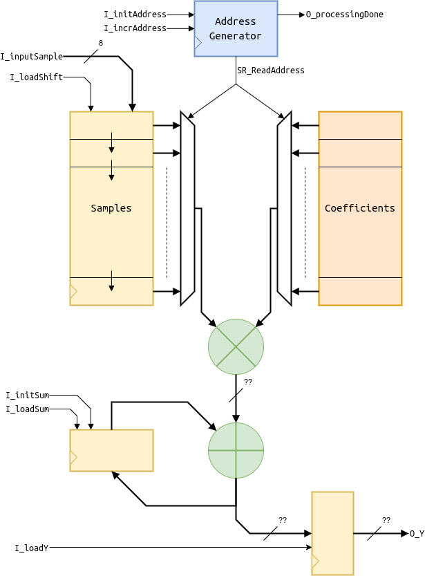
Note
Cette architecture est à décrire dans fichier VHDL operativeUnit.vhd
Description du travail attendu⚓
Travail préparatoire⚓
Warning
Il est obligatoire de compléter le diagramme de l’automate sur la base des documents fournis. Pour cela, il faut comprendre l’interaction entre le contrôle et la partie opérative. Les états sont déjà proposés, à vous de fournir les conditions de transition entre les états (les différentes expressions Ci sur le diagramme) et les valeurs des instructions à déclencher pour chaque état, sur la base de l’exemple fourni pour l’état OUTPUT.
Travail en salle⚓
Vous utiliserez le logiciel Xilinx Vivado pour décrire et synthétiser votre circuit sur la base des fichiers disponibles sur la plateforme Moodle de l’UV Électronique, section Travaux Pratiques. Lors des deux séances, vous compléterez le code fourni des parties de contrôle et opérative, puis vous testerez sur carte le résultat de votre réflexion à chaque séance et déposerez sur le dépôt moodle de votre salle les fichiers VHDL que vous aurez édités. Pour valider l’effet du filtre, vous pourrez tester son efficacité de réduction de bruit de quantification par l’intermédiaire de différentes configurations expliquées en séance.
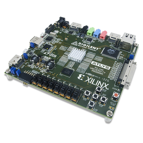
Le circuit à configurer est un FPGA Xilinx Artix 7 qui est intégré sur la carte Digilent Nexys Video représentée en figure 2.2.4 et comprenant, outre le FPGA, de nombreux périphériques.
La documentation de la carte est disponible sur la page Moodle de l’UV Électronique. Cette documentation vous est utile pour comprendre l’usage des périphériques.
De la description au test de l’unité de contrôle⚓
Récupération du projet gitlab sur https://gitlab-df.imt-atlantique.fr⚓
Un dépôt git a été créé pour chaque étudiant sur l'instance gitlab de la DFVS de l'école https://gitlab-df.imt-atlantique.fr. Il contient les sources VHDL nécessaires au projet, des scripts pour gérer le projet Vivado, et un compte-rendu.md permettant de répondre aux questions. Si vous travaillez en binôme, choisissez un des deux, et ajoutez votre collègue en tant que owner sur le projet dans gitlab.
Tout d'abord, il faut ouvrir un terminal : Ctrl+Alt+T
- Création d'un répertoire pour l'UE Électronique et déplacement dedans :
Warning
Pensez à adapter le chemin de la commande ci-dessous à vos propres besoins
1 2 | |
- Clonage en local du dépôt git
Warning
Pensez à adapter le lien de la commande ci-dessous en fonction du dépôt sur gitlab
1 | |
git clone permet de récupérer l'entièreté du dépôt git avec son historique de modifications.
Vous pouvez observer facilement ce cette commande a permit de télécharger avec la commande ls -alsh dans le répertoire tp-filtre-etudiant-$USER.
Création d’un projet Vivado⚓
Warning
Ne mettez jamais d'espaces, d'accent ni de caractères spéciaux dans les noms de fichiers ou de répertoires ! Ceci est valable en général, sur Windows comme sur Linux. Et fait planter Vivado en ce qui nous concerne ici.
Retour au répertoire racine utilisateur et lancement de Vivado 2020.2 :
1 2 | |
Un script TCL est fourni pour automatiser la création du projet. Pour l'utiliser, il faut :
- se placer dans la console Tcl de Vivado, tout en bas de la fenêtre.
- se placer dans le répertoire
Projetgrâce à la commandecd:cd tp-filtre-etudiant-$USER/proj(ici il faut manuellement remplacer$USERpar votre login) - taper la commande
source ./create_project.tcl
Warning
Il ne faut pas d'accents, d'espaces ni de caractère spéciaux dans le chemin et le nom des fichier
Note
les commandes cd, ls, pwd de shell sont utilisables dans cette console
Description VHDL⚓
Vous devez remplacer dans le fichier controlUnit.vhd les parties _BLANK_ par le code VHDL approprié en respectant l’automate que vous avez complété en travail préparatoire.
Question filtre 1, (réponse à compléter dans le fichier docs/compte-rendu.md)
Combien de processus sont utilisés et de quelles natures sont-ils ? Comment les différenciez-vous ?
Simulation⚓
Une unité opérative ”compilée” est disponible pour simuler et tester votre description de la partie contrôle. Votre projet doit donc à ce stade contenir le fichier operativeUnitIP.v à la place du fichier operativeUnit.vhd que vous modifierez bientôt...
La séquence attendue en sortie du filtre est (sous forme d’entiers signés) :
0 2 3 6 10 15 20 24 26 26 24 20 15 10 6 3 2 0 0 0 1 2 3 5 7 7 8 4 -1 -8 -17 -27 -38 -49 -61 -71 -82 -93 -101 -107 -112 -113 -116.
Simulez alors le testbench associé au fichier tb_firUnit.vhd.
Question filtre 2, (réponse à compléter dans le fichier docs/compte-rendu.md)
La simulation vous permet-elle de valider votre description VHDL ? Justifiez.
Test⚓
Déroulez le flot de conception jusqu’à production du bitstream que vous transférez sur Moodle dans le dépôt prévu pour votre salle. Il peut ainsi être testé sur la carte à disposition connectée au PC prof. L’entrée Line-in peut être connectée à toute source analogique par un jack 3.5mm (sortie d’un smartphone ou d’une carte audio de PC) et la sortie Line-out doit être connectée à casque ou un amplificateur audio.
La carte Nexys VIDEO est configurée de telle sorte que les 5 interrupteurs SW7 à SW3 en bas à gauche ainsi que le bouton central BTNC en bas à droite sont utilisés.
Lorque l’utilisateur presse le bouton BTNC, il peut écouter le flux audio d’origine codé sur 24 bits et non filtré, sinon il écoute le flux audio sous-quantifié au mieux sur 8 bits en entrée ou sortie du filtre. L’interrupteur SW7 contrôle justement cette sélection. Lorsque SW7=ON, l’utilisateur écoute la sortie du filtre, sinon il écoute l’entrée sous-quantifiée du filtre sur 8 bits au mieux.
La sous-quantification est gérée par la combinaison des interrupteurs SW6 à SW3. Le nombre de bits retirés sur les 8 à l’entrée du filtre est codé en binaire naturel par MSB=SW5 SW4 LSB=SW3 et SW6 permet de sélectionner le type d’arrondi (si ON, au plus proche, sinon par troncature).
Question filtre 3 (réponse à compléter dans le fichier docs/compte-rendu.md)
Validez-vous la conception de l’unité de contrôle ?
De la description au test de l’unité opérative⚓
Description VHDL⚓
Vous devez enlever le fichier operativeUnitIP.v et ajouter le fichier operativelUnit.vhd dans le projet. Remplacez les parties _BLANK_ par le code VHDL approprié en respectant le https://tp-vhdl.gitlab-pages.imt-atlantique.fr/filtre/#schema-de-larchitecture-de-lunite-operative
Question 16 (réponse à compléter dans le fichier docs/compte-rendu.md)
Combien de processus sont utilisés et de quelles natures sont-ils ?
Simulation⚓
Votre projet doit maintenant contenir le fichier operativeUnit.vhd à la place du fichier operativeUnitIP.v. Simulez alors le testbench associé au fichier tb_firUnit.vhd.
Question filtre 4 (réponse à compléter dans le fichier docs/compte-rendu.md)
La simulation vous permet-elle de valider votre description VHDL ? Sinon, quel élément pose problème ? Comment pouvez-vous le corriger ? Justifiez
Test⚓
Déroulez le flot de conception jusqu’à production du bitstream que vous transférez sur Moodle dans le dépôt prévu pour votre salle. Il peut ainsi être testé sur la carte à disposition connectée au PC prof.
Question filtre 5 (réponse à compléter dans le fichier docs/compte-rendu.md)
Validez-vous la conception de l’unité opérative ? Sinon, quel élément pose problème ? Comment pouvez-vous le corriger ?
lab 1 design of a digital filter⚓
VHDL Cheat⚓
https://memo-vhdl.gitlab-pages.imt-atlantique.fr/
gitlab repository⚓
A gitlab repository tp-filtre-etudiant is available in your gitlab space on https://gitlab-df.imt-atlantique.fr, in the group corresponding to the course followed.
To manipulate it (clone, add, commit, push, pull), please refer to the page Git and Gitlab .
If no repository creation is planned for your course, or if you want to do this lab freely. The reference repository is here: https://gitlab.imt-atlantique.fr/tp-vhdl/tp-filtre-etudiant
Objective⚓
This lab offers a brief introduction to the design of digital integrated circuits, by discovering the integration of an essential function in information and signal processing: filtering. Starting from an algorithm, you will have to describe an architecture in VHDL (a language dedicated to electronics), perform its synthesis and finally test this architecture on a reconfigurable Field-Programmable Gate Array (FPGA) circuit.
Note
A VHDL code will be partially proposed to you, you will have to complete it, based on the preparatory work requested.
Info
For your information, know that FPGAs have held an essential place in high-end audiophile systems (such as those from PSaudio) for several years and are beginning to break into "consumer" products with high-resolution formats that FPGAs can fully exploit (as in the Chord Mojo for audiophile players).
Filtering of sound signals⚓
Description of the algorithm⚓
A sound signal s(t), continuous in time and value, is commonly sampled at 44.1kHz for musical applications (22kHz for radio and 8kHz for the telephone) and then digitized on a limited number of bits (8, 16 or 24 bits are common). The result is then a sequence of samples \(S(k)\). This signal can be filtered for many reasons, such as to accentuate certain effects or correct imperfections for example. In this lab, we will only consider simple linear filters with Finite Impulse Response (FIR). Applying such a filter h to a continuous signal \(s(t)\) would require an analog filter circuit capable of performing the convolution \(h \times s(t)\). To perform it on a digital signal, we will unroll an equivalent calculation, replacing the integral of the convolution with a discrete sum over a finite depth of N samples and keeping the multiplication of the convolution. Thus, for any sample \(S(k)\), the filtered sample \(S'(k)\) is such that:
This equation can be translated into an algorithm applied to any sample \(S(k)\) on the input S_IN which is considered valid by the filter when a control binary signal VALID goes from 0 to 1:
1 2 3 4 5 6 7 8 9 10 11 12 13 14 15 16 17 18 19 20 21 22 23 24 25 26 | |
The output signal S_OUT changes state at the same frequency as S_IN.
Description of the circuit architecture⚓
The digital filtering processor can be implemented with two modules, an operative unit and a control unit (described by a finite state automaton), both provided incomplete. These two combined modules reflect the previously described algorithm. Each operation corresponds to the execution of an instruction given by the automaton to the operative part (loadShift, initAddress, incAddress, initSum, loadSum, loadOutput). The operative part can send state information to the control automaton, such as a processingDone bit indicating that the last product \(S(k − i) × H(i)\) is being processed.
Architecture diagram of the filtering unit:⚓
Note
Corresponds to the VHDL file FirUnit.vhd that to eventually be completed
Finite state machine diagram:⚓
Note
This diagram is to be completed in order to then complete the VHDL file controlUnit.vhd. To do this, you can use the file FSM.drawio available in the git repository, it is the file docs/img/FSM.drawio with the tool https://app.diagrams.net/. Then update the file FSM.png by exporting the diagram FSM.drawio previously updated.
Architecture diagram of the operative unit:⚓
Note
This architecture is to be described in the VHDL file operativeUnit.vhd
Description of the expected work⚓
Preparatory work⚓
Warning
It is mandatory to complete the automaton diagram based on the documents provided. To do this, you need to understand the interaction between control and the operative part. The states are already proposed, you have to provide the transition conditions between the states (the different expressions Ci on the diagram) and the values of the instructions to trigger for each state, based on the example provided for the OUTPUT state.
Work in the classroom⚓
You will use the Xilinx Vivado software to describe and synthesize your circuit based on the files available on the Moodle platform of the UV Électronique, Travaux Pratiques section. During the two sessions, you will complete the provided code of the control and operative parts, then you will test the result of your reflection at each session and deposit on the moodle repository of your room the VHDL files that you will have edited. To validate the effect of the filter, you can test its quantization noise reduction efficiency through different configurations explained in class.
The circuit to be configured is a Xilinx Artix 7 FPGA which is integrated on the Digilent Nexys Video board shown in figure 2.2.4 and including, in addition to the FPGA, many peripherals.
The documentation of the board is available on the Moodle page of the UV Électronique. This documentation is useful to understand the use of the peripherals.
From description to control unit test⚓
Retrieving the gitlab project on https://gitlab-df.imt-atlantique.fr⚓
A git repository has been created for each student on the school's DFVS gitlab instance https://gitlab-df.imt-atlantique.fr. It contains the VHDL sources necessary for the project, scripts to manage the Vivado project, and a compte-rendu.md file to answer the questions. If you work in pairs, choose one of the two, and add your colleague as an owner on the project in gitlab.
First, open a terminal: Ctrl+Alt+T
- Create a directory for the UE Électronique and move into it:
Warning
Remember to adapt the path of the command below to your own needs
1 2 | |
- Clone the git repository locally
Warning
Remember to adapt the link of the command below according to the repository on gitlab
1 | |
git clone command allows you to retrieve the entire git repository with its history of modifications.
You can easily see that this command has allowed you to download with the ls -alsh command in the tp-filtre-etudiant-$USER directory.
Creating a Vivado project⚓
Warning
Never put spaces, accents or special characters in file or directory names! This is true in general, on Windows as well as on Linux. And it crashes Vivado in our case here.
Return to the user's root directory and launch Vivado 2020.2:
1 2 | |
A TCL script is provided to automate the project creation. To use it, you need to:
- go to the Tcl console of Vivado, at the bottom of the window.
- go to the
Projetdirectory with thecdcommand:cd tp-filtre-etudiant-$USER/proj(here you have to manually replace$USERwith your login) - type the command
source ./create_project.tcl
Warning
There should be no accents, spaces or special characters in the path and file name
Note
shell commands cd, ls, pwd are usable in this console
VHDL description⚓
You must replace in the file controlUnit.vhd the parts _BLANK_ with the appropriate VHDL code respecting the automaton that you have completed in preparatory work.
Question filter 1, (answer to be completed in the file docs/compte-rendu.md)
How many processes are used and what are their natures? How do you differentiate them?
Simulation⚓
A "compiled" operative unit is available to simulate and test your description of the control part. Your project must therefore at this stage contain the file operativeUnitIP.v instead of the file operativeUnit.vhd that you will soon modify...
The expected sequence at the output of the filter is (in the form of signed integers):
0 2 3 6 10 15 20 24 26 26 24 20 15 10 6 3 2 0 0 0 1 2 3 5 7 7 8 4 -1 -8 -17 -27 -38 -49 -61 -71 -82 -93 -101 -107 -112 -113 -116.
Simulate the testbench associated with the file tb_firUnit.vhd.
Question filter 2, (answer to be completed in the file docs/compte-rendu.md)
Does the simulation allow you to validate your VHDL description? Justify.
Test⚓
Run the design flow until the bitstream is produced and transfer it to Moodle in the repository provided for your room. It can then be tested on the available board connected to the PC prof. The Line-in input can be connected to any analog source via a 3.5mm jack (output from a smartphone or a PC audio card) and the Line-out output must be connected to a headset or an audio amplifier.
The Nexys VIDEO board is configured so that the 5 switches SW7 to SW3 at the bottom left and the central button BTNC at the bottom right are used.
When the user presses the BTNC button, he can listen to the original audio stream coded on 24 bits and not filtered, otherwise he listens to the audio stream under-quantified at best on 8 bits at the input or output of the filter. The SW7 switch precisely controls this selection. When SW7=ON, the user listens to the filter output, otherwise he listens to the input under-quantified by the filter on 8 bits at best.
Under-quantization is managed by the combination of switches SW6 to SW3. The number of bits removed from the 8 at the input of the filter is coded in natural binary by MSB=SW5 SW4 LSB=SW3 and SW6 allows to select the type of rounding (if ON, to the nearest, otherwise by truncation).
Question filter 3 (answer to be completed in the file docs/compte-rendu.md)
Do you validate the design of the control unit?
From description to test of the operative unit⚓
VHDL description⚓
You must remove the file operativeUnitIP.v and add the file operativelUnit.vhd to the project. Replace the parts _BLANK_ with the appropriate VHDL code respecting the https://tp-vhdl.gitlab-pages.imt-atlantique.fr/filtre/#schema-de-larchitecture-de-lunite-operative
Question 4 (answer to be completed in the file docs/compte-rendu.md)
How many processes are used and what are their natures?
Simulation⚓
Your project must now contain the file operativeUnit.vhd instead of the file operativeUnitIP.v. Then simulate the testbench associated with the file tb_firUnit.vhd.
Question filter 5 (answer to be completed in the file docs/compte-rendu.md)
Does the simulation allow you to validate your VHDL description? If not, what is the problem? How can you fix it? Justify
Test⚓
Run the design flow until the bitstream is produced and transfer it to Moodle in the repository provided for your room. It can then be tested on the available board connected to the PC prof.
Question filter 6 (answer to be completed in the file docs/compte-rendu.md)
Do you validate the design of the operative unit? If not, what is the problem? How can you fix it?