TP de conception d'un jeu de Loto⚓
VHDL Cheat⚓
https://memo-vhdl.gitlab-pages.imt-atlantique.fr/
Dépôt Gitlab associé⚓
Un dépôt gitlab tp-loto-etudiant est disponible dans votre espace gitlab sur https://gitlab-df.imt-atlantique.fr, dans le groupe correspondant à l'enseignement suivi.
Pour le manipuler (clone, add, commit, push, pull), veuillez vous référer à la page Git et Gitlab .
Présentation du circuit de LOTO⚓
Fonctions principales⚓
Le circuit à concevoir permet de réaliser un tirage aléatoire de type LOTO de 6 nombres différents compris entre 1 et 49. Le principe de fonctionnement est le suivant : pour tirer au sort un nombre, il faut appuyer sur un bouton, puis le relâcher. Si le nombre n’est pas déjà sorti, il s’affiche et une diode verte indique à l’utilisateur de passer au nombre suivant, le nombre tiré étant sauvegardé dans un registre de la mémoire. Dans le cas contraire, une diode rouge s’allume pour indiquer à l’opérateur qu’il doit recommencer le tirage. Les nombres en mémoire défilent en boucle (chiffre désignant le registre lu, chiffre des dizaines du nombre dans le registre, puis chiffre des unités) sur des afficheurs 7-segments. En utilisant un interrupteur, on peut bloquer l’affichage de la mémoire sur un registre.
Cible matérielle⚓
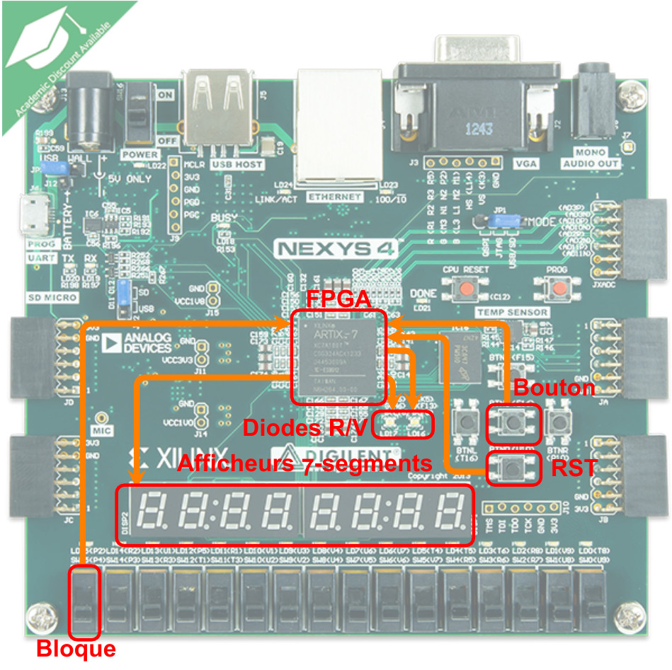
Le circuit à configurer est un FPGA Xilinx Artix7 (xc7a100tcsg-1) qui est inséré sur la carte Digilent Nexys4 représentée ci-dessous et comprenant, outre le FPGA, les LED tri-colores, les afficheurs à 7 segments, un quartz à 100MHz pour fournir un signal d’horloge, quelques composants servant en particulier à commander les afficheurs et deux boutons : l’un pour faire une remise à 0 du circuit, l’autre pour faire le tirage des nombres.
Circuit complet de Loto⚓
Principe de fonctionnement⚓
Avant le tirage des nombres, il faut initialiser toutes les bascules du circuit en positionnant I_rst à 1, puis en le remettant à 0. Les afficheurs doivent alors tous afficher 0. Le tirage au sort d’un nombre se fait avec un compteur synchrone comptant de 1 à 49 en boucle. Le compteur progresse tant que I_button = 1. Dès que I_button = 0, le compteur se bloque dans son état. Le circuit doit alors :
- mémoriser l’état du compteur dans un registre si le nombre n’a pas encore été tiré, et allumer la LED verte,
- allumer la LED rouge si le nombre a déjà été tiré.
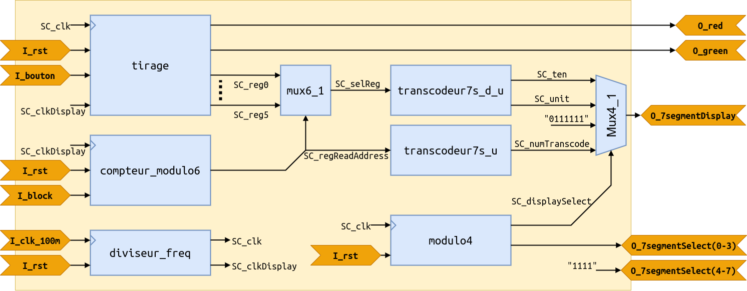
Les six nombres sont mémorisés dans six registres de sortie alimentant les 2 afficheurs (un pour la dizaine et un pour l’unité) de la carte. Quand le sixième nombre valide est tiré, les LED rouge et verte doivent clignoter alternativement (au rythme d’une demi-seconde d’éclairage) et un nouveau tirage ne peut commencer qu’en actionnant I_rst.
Module de tirage⚓
Rôles des entrées⚓
| Entrées | Description |
|---|---|
I_clk |
horloge du circuit fournie par un circuit diviseur de fréquence sur la base d’un signal issu d’un quartz à 100 MHz |
I_clk_display |
signal périodique de l’ordre de 1Hz, fourni par le diviseur de fréquence susmentionné |
I_rst |
remise à zéro du circuit, en particulier des afficheurs |
I_button |
tirage au sort du nombre |
Rôles des sorties⚓
| Entrées | Description |
|---|---|
O_l_red |
alimente une LED rouge indiquant qu’il faut recommencer le tirage du nombre. |
O_l_red |
alimente une LED verte indiquant qu’il faut effectuer le tirage du nombre suivant. |
O_reg0 à O_reg5 |
nombres en mémoire qui devront être transmis à des afficheurs 7 segments. |
Ce module devra être interfacé avec les boutons et afficheurs, ce qui requiert quelques modules supplémentaires qui ne sont pas détaillés ici, mais dont vous pouvez explorer le code VHDL pour comprendre leur fonctionnement.
Travaux pratiques en séance⚓
Info
N.B. : Les captures d’écran sont réalisées avec Vivado 2018.3. Des variations peuvent apparaître avec d’autres versions mais la logique de l’outil est identique. Les pratiques et notions proposées sont basiques. Au fur et à mesure de la montée en compétence, vos pratiques peuvent (doivent) évoluer !
Récupération du projet gitlab sur https://gitlab-df.imt-atlantique.fr⚓
Un dépôt git a été créé pour chaque étudiant sur l'instance gitlab de la DFVS de l'école https://gitlab-df.imt-atlantique.fr. Il contient les sources VHDL nécessaires au projet, des scripts pour gérer le projet Vivado, et un compte-rendu.md permettant de répondre aux questions. Si vous travaillez en binôme, choisissez un des deux, et ajoutez votre collègue en tant que owner sur le projet dans gitlab.
Tout d'abord, il faut ouvrir un terminal : Ctrl+Alt+T
- Création d'un répertoire pour l'UE Électronique et déplacement dedans :
Warning
Pensez à adapter le chemin de la commande ci-dessous à vos propres besoins
1 2 | |
- Clonage en local du dépôt git
Warning
Pensez à adapter le lien de la commande ci-dessous en fonction du dépôt sur gitlab
1 | |
La commande git clone permet de récupérer l'entièreté du dépôt git avec son historique de modifications.
Vous pouvez observer facilement ce cette commande a permis de télécharger avec la commande ls -alsh dans le répertoire tp-loto-etudiant-$USER.
Gestion du projet sous Vivado⚓
Warning
Ne mettez jamais d'espaces, d'accent ni de caractères spéciaux dans les noms de fichiers ou de répertoires ! Ceci est valable en général, sur Windows comme sur Linux. Cela fait est bloquant avec Vivado en ce qui nous concerne ici.
Ouverture de Vivado⚓
Sous Linux, ouvrez un Terminal, déplacez vous dans le répertoire de travail du dépôt, avec la commande cd, que vous avez cloné et exécutez la commande suivante :
1 | |
Création d’un nouveau projet⚓
Cliquez sur Create New Project pour lancer l’assistant (wizard) de création de projet, puis cliquez sur Next sur la fenêtre qui apparaît alors. Dans la fenêtre suivante :
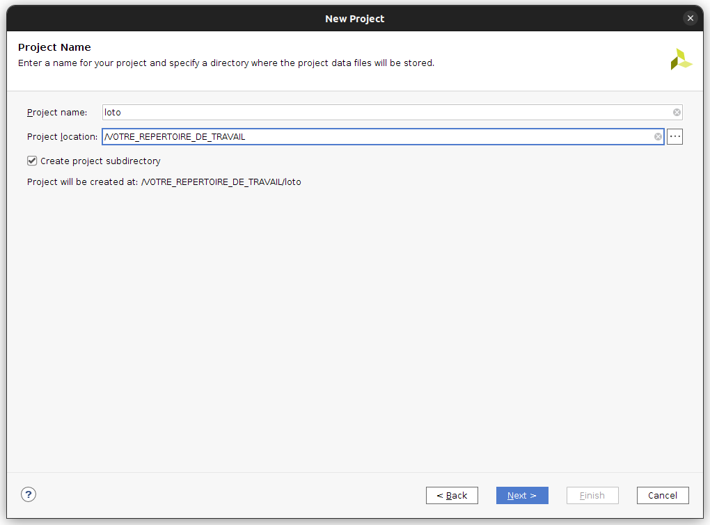
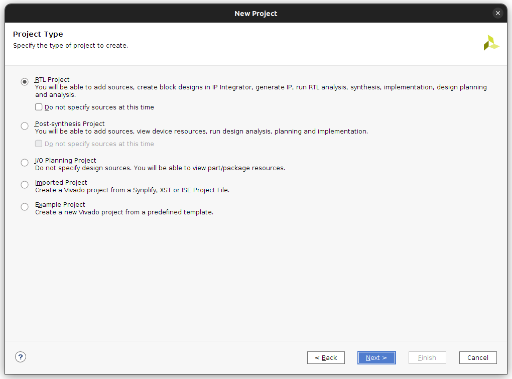
renseignez le nom de votre projet et votre répertoire de travail. A la fenêtre suivante, sélectionnez RTL Project pour créer un projet qui acceptera des sources VHDL.
Ajout des fichiers sources et des contraintes⚓
Validez encore par Next pour passer à la fenêtre suivante qui vous demande vos fichiers sources. Cliquez sur Add Files et sélectionnez alors tous les fichiers VHDL (en extension .vhd) de votre dépôt git puis modifiez le mode du fichier de test loto_tb.vhd en mode Simulation Only :
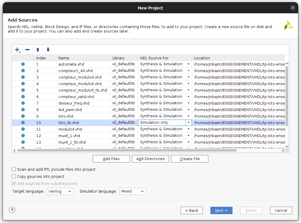
Cliquez sur Next pour valider.
Sélection du FPGA utilisé⚓
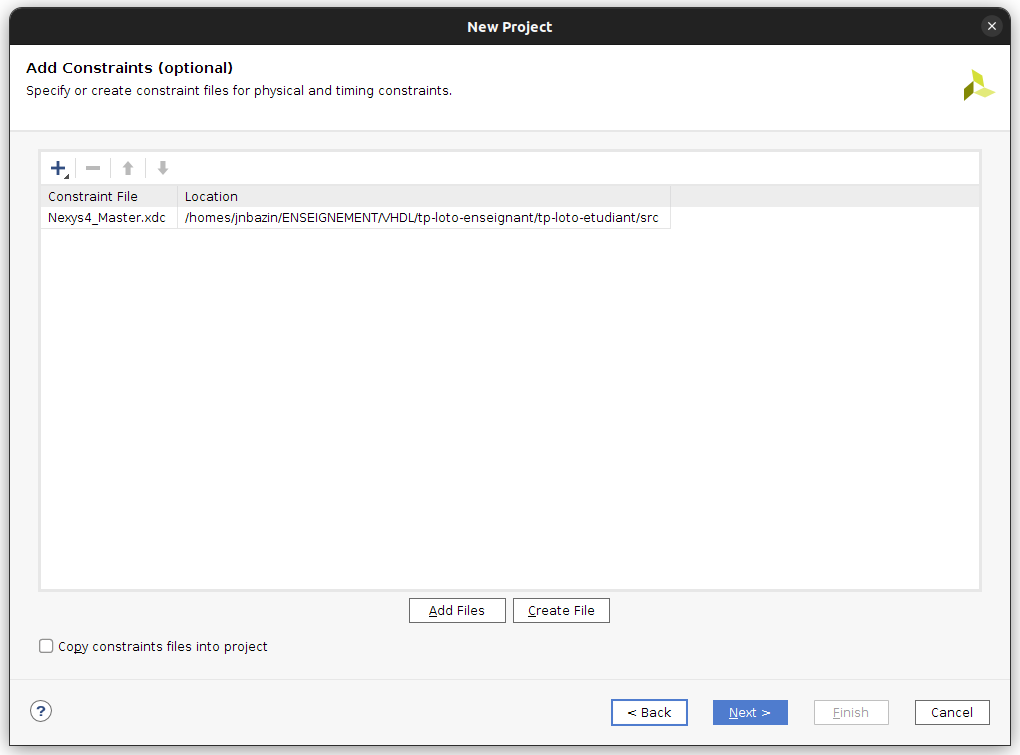
Apparaît alors la fenêtre Add Constraints. Sélectionnez le fichier Nexys4DDR-Master.xdc ou Nexys4_Master.xdc selon la version de carte dont vous disposez pour ce TP (une Nexys4 ou une Nexys4DDR) :
Après validation apparaît la fenêtre de sélection de la cible matérielle FPGA que vous renseignez tel qu’indiqué sur la figure suivante :
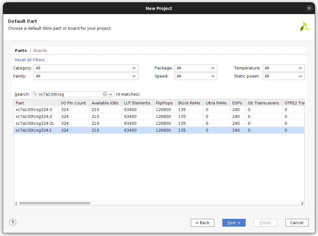
Cela vous permet de choisir le FPGA de la carte Nexys4 (ou Nexys4DDR). La fenêtre suivante résume votre projet et doit être identique à celle ci :
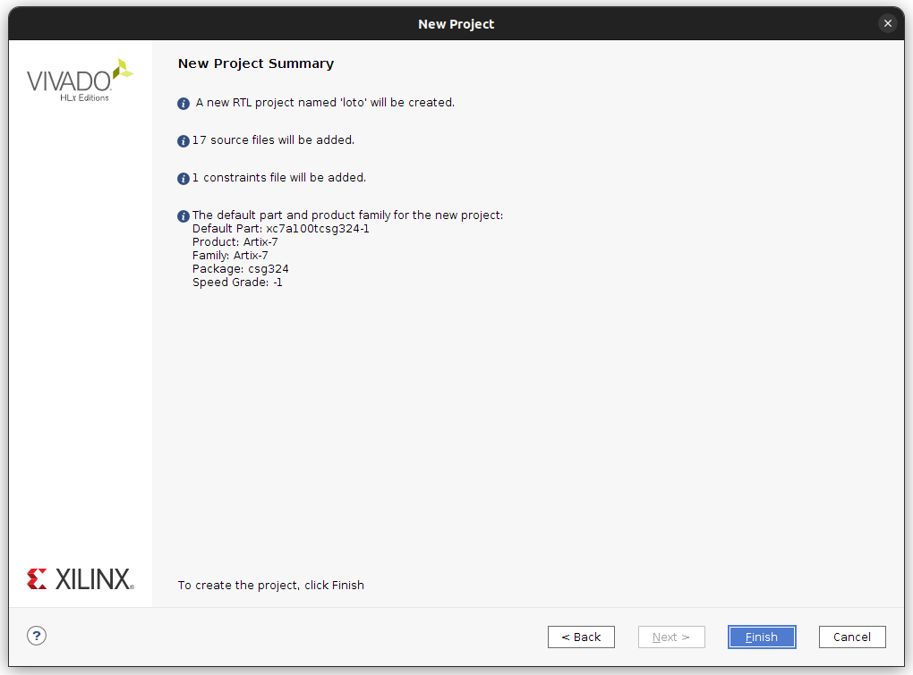
Le projet est ensuite créé et l’interface projet de Vivado se lance :
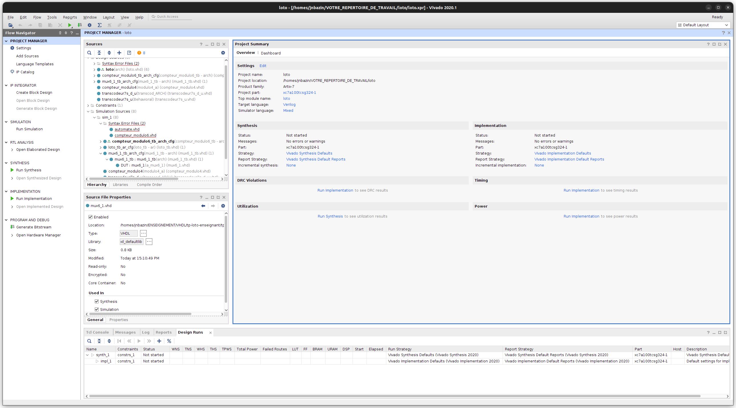
Description partielle du premier module combinatoire en VHDL⚓
Dans la fenêtre PROJECT MANAGER / Sources développez l’item Design Sources / Syntax Error Files. Ouvrez le fichier mux6_1.vhd, dont certaines parties ont été remplacées par _BLANK_. Ce fichier permet de décrire une fonction combinatoire classique de multiplexage de 6 entrées {I_0, I_1, I_2, I_3, I_4, I_5} vers une sortie O_mux6, commandée par un signal I_sel sur 3 bits. En vous inspirant des codes présentés sur https://memo-vhdl.gitlab-pages.imt-atlantique.fr/synthesizable-vhdl/#multiplexer, remplacez les sections _BLANK_ par du code approprié.
Question Loto 1, (réponse à compléter dans le fichier docs/compte-rendu.md)
Quels sont les signaux à renseigner dans la liste de sensibilité (si vous utilisez un process explicite) ?
Question Loto 2, (réponse à compléter dans le fichier docs/compte-rendu.md)
Que se passe-t-il si le test au coeur du process (la succession de "when" ) est incomplet, c’est-à-dire s’il ne couvre pas toutes les combinaisons d’entrées du module ? Est-ce grave ?
Simulation VHDL du premier module combinatoire⚓
Pour valider ensuite votre module de multiplexage, vous le simulez avec l’outil XSIM de Vivado. Pour cela un fichier de test vous est proposé : mux6_1_tb.vhd, aussi disponible par la fenêtre Sources, onglet Simulation Sources sim_1 /mux6_1_tb_arch_cfg. Sélectionnez ce module.
Puis, cliquez sur le boution droit de la souris pour faire apparaître le menu contextuel et cliquez sur Set as Top. Ainsi, ce module pourra être simulé en cliquant dans le panneau de gauche Flow Navigator / Project Manager sous l’onglet Simulation sur la commande Run Simulation puis Run Behavioural Simulation.
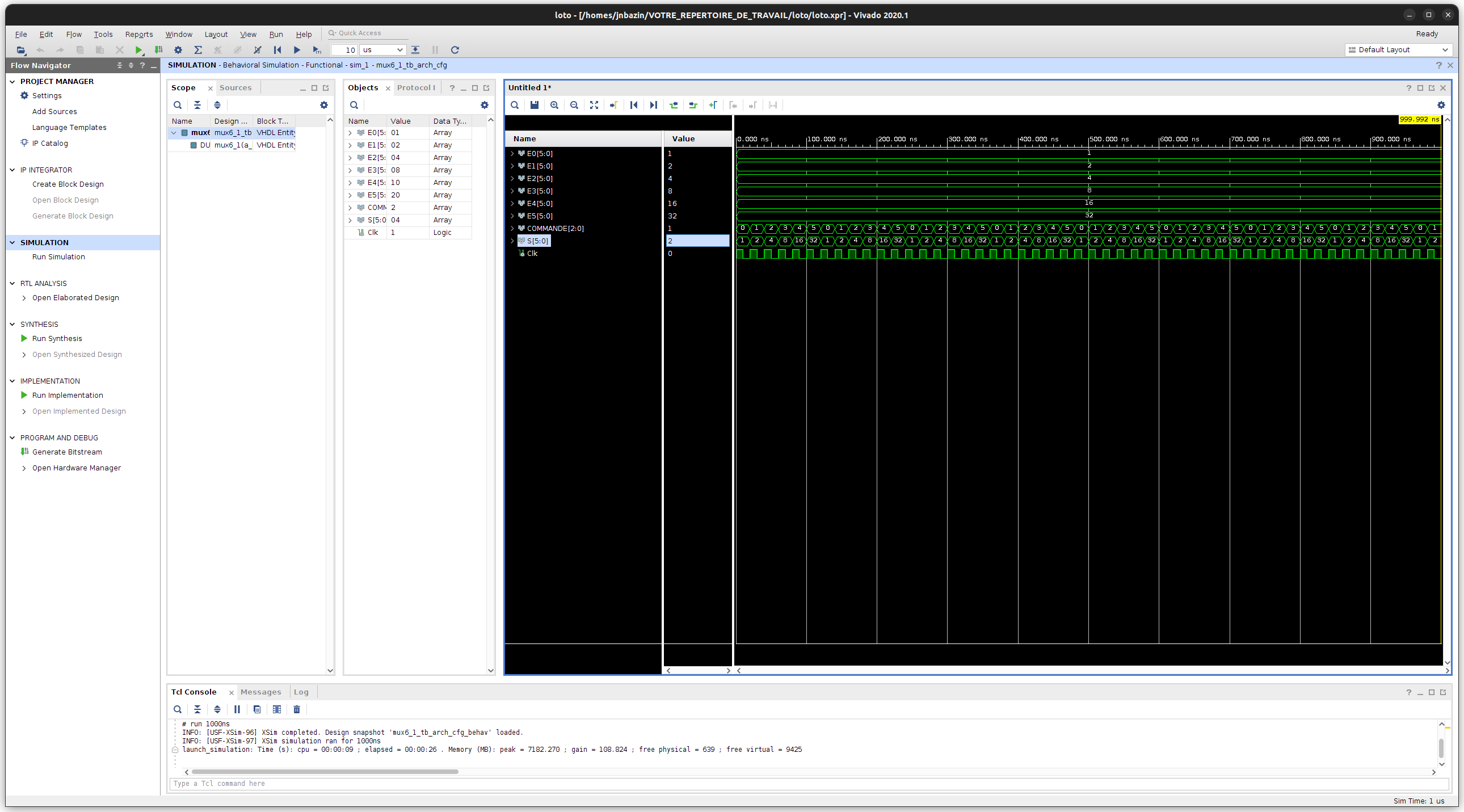
La fenêtre ci-dessous apparaît alors. Cliquez sur Zoom Fit puis ajustez le zoom jusqu’à pouvoir analyser le chronogramme de la simulation et ainsi vérifier que votre description VHDL fournit le comportement attendu. N’hésitez pas à modifier le radix d’affichage d’un signal en décimal en cliquant sur le nom d’un signal, avec le bouton droit de la souris, puis sur Radix -> unsigned decimal.
Question Loto 3, (réponse à compléter dans le fichier docs/compte-rendu.md)
Cette simulation est-elle concluante ? Est-elle suffisante pour valider le module ? Justifiez.
Description partielle du premier module séquentiel en VHDL⚓
Quittez la simulation en fermant la sous-fenêtre de simulation. Ensuite, dans la fenêtre PROJECT MANAGER / Sources développez l’onglet Design Sources / Syntax Error Files. Ouvrez le fichier compteur_modulo6.vhd, dont certaines parties ont été remplacées par _BLANK_. Ce fichier permet de décrire une fonction séquentielle classique de comptage entier modulo 6. En vous inspirant du modèle fourni pour un compteur modulo 4 fourni dans le fichier compteur_modulo4.vhd, remplacez les sections _BLANK_ par du code approprié.
Question Loto 4, (réponse à compléter dans le fichier docs/compte-rendu.md)
Quel(s) signal(aux) doit on renseigner dans la liste de sensibilité de ce processus séquentiel ? Pourquoi ?
Question Loto 5, (réponse à compléter dans le fichier docs/compte-rendu.md)
Que se passe-t-il si le test est incomplet, c’est-à-dire s’il ne couvre pas toutes les combinaisons d’entrées du module ? Est-ce grave ici ?
Simulation VHDL du premier module séquentiel⚓
Pour valider de nouveau votre description VHDL, vous devez simuler le module avec le fichier de test proposé : compteur_modulo6_tb.vhd.
Question Loto 6, (réponse à compléter dans le fichier docs/compte-rendu.md)
Ce test est-il concluant ? Est-il suffisant pour valider le module ? Justifiez.
Description d’un automate ou machine à états finie⚓
Voici le diagramme de l’automate fini qui gère le tirage :
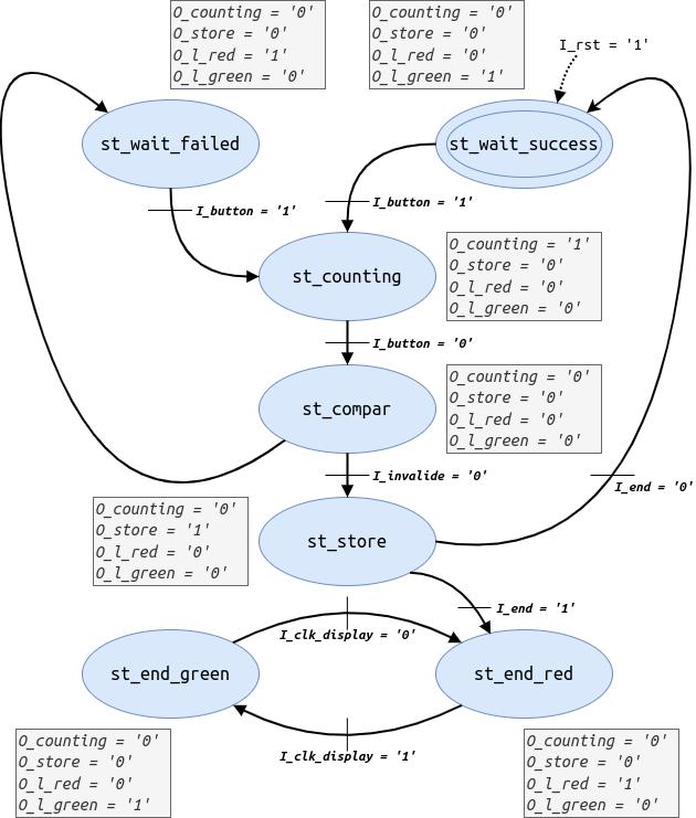
Vous allez décrire cet automate en VHDL. Pour ce faire, dans la fenêtre PROJECT MANAGER / Sources développez l’onglet Design Sources / Syntax Error Files. Ouvrez le fichier automate.vhd, dont certaines parties ont été remplacées par _BLANK_ et corrigez les.
Question Loto 7, (réponse à compléter dans le fichier docs/compte-rendu.md)
Combien de processus avez-vous décris ?
Question Loto 8, (réponse à compléter dans le fichier docs/compte-rendu.md)
De quel(s) type(s) sont-ils
Question Loto 9, (réponse à compléter dans le fichier docs/compte-rendu.md)
Serait-il possible de décrire cette machine d'état de manière différente, en terme de nombre et de type de process ?
Simulation du circuit complet⚓
Pour valider par simulation l’automate et les autres modules, vous devez simuler l’intégralité du circuit de loto. Passez donc le module loto_tb_ar_cfg en TOP dans la partie Simulation Sources et simulez le circuit comme de la même manière que pour les circuits précédents.
Question Loto 10, (réponse à compléter dans le fichier docs/compte-rendu.md)
Ce test est-il concluant ? Justifiez.
Élaboration, synthèse et implantation du circuit sur FPGA⚓
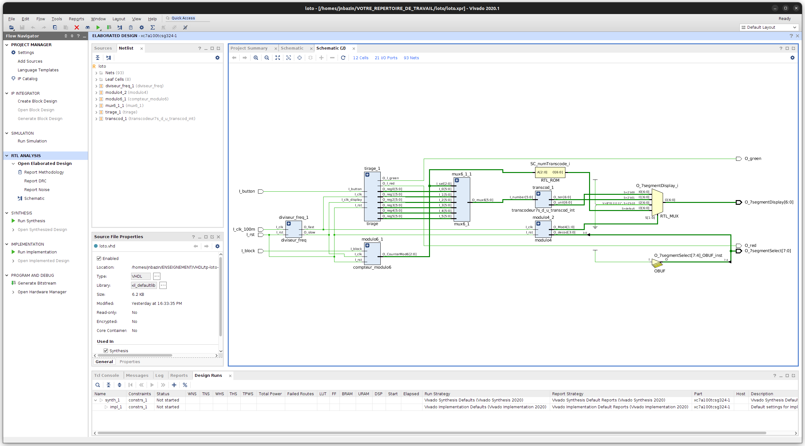
Maintenant que le circuit est validé en simulation, vous allez passer au test sur carte, si vous passez les phases de compilation matérielle que sont l’élaboration, la synthèse, le placement et le routage avec succès ! Passez le module loto.vhd en TOP dans la partie Design Sources. N’oubliez pas cette étape ! Dans le panneau de gauche Flow Navigator / Project Manager sous l’onglet RTL Analysis, cliquez sur la commande Open Elaborated Design puis analysez le circuit inféré par l’outil.
Question Loto 11, (réponse à compléter dans le fichier docs/compte-rendu.md)
Le circuit inféré par l’outil est-il conforme à l’attendu ? Sinon, en quoi diffère-t-il et est-ce lié à une erreur de description VHDL ?
Ensuite, toujours dans le panneau de gauche Flow Navigator / Project Manager, cliquez sous l’onglet Synthesis sur la commande Run Synthesis et acceptez ensuite les paramètres par défaut. Une fois la synthèse finie, Vivado vous propose trois actions à suivre : choisissez View Reports. Dans le panneau du bas apparaît l’onglet Reports, double-cliquez sur le premier rapport de la liste : synth_1_synth_report_utilization_0.
Question Loto 12, (réponse à compléter dans le fichier docs/compte-rendu.md)
Quelles sont les ressources utilisées sur le FPGA ? En quelle quantité/proportion des ressources disponibles ? Des LATCHES sont-ils utilisés ? Est-ce positif ou pas, pourquoi ?
Ensuite, vous revenez au panneau de gauche Flow Navigator / Project Manager, cliquez sous l’onglet Implementation sur la commande Run Implementation et acceptez ensuite les paramètres par défaut. Lorsque cette phase de compilation matérielle est finie, Vivado vous propose trois options pour la suite, sélectionnez Generate Bitstream et validez ensuite les options par défaut. L’outil vous produit alors un fichier de configuration du FPGA qui spécifie comment le FPGA sera utilisé pour fournir le circuit conçu en VHDL et contraint par le fichier qui spécifie les entrées/sorties.
Test du circuit sur FPGA⚓
Une fois la génération du bitstream finie, vous pouvez sélectionner l’option Open Hardware Manager. Connectez une carte sur un port USB de votre ordinateur et assurez-vous que l’interrupteur Power est sur ON si aucune diode ne s’allume avant d’appeler un enseignant
Dans la fenêtre Hardware manager, cliquez sur Open target dans le bandeau vert puis sur Auto Connect. Votre FPGA apparaît alors dans une sous-fenêtre Hardware.
Toujours dans le bandeau vert, cliquez sur Program device pour transférer le bitstream sur le FPGA qui sera ensuite configuré pour réaliser le circuit de Loto que vous avez décrit.
Testez !
Question Loto 13, (réponse à compléter dans le fichier docs/compte-rendu.md)
Le tirage est-il aléatoire pour un humain ? pour une machine ? Justifiez.
lab of loto game design⚓
VHDL Cheat⚓
https://memo-vhdl.gitlab-pages.imt-atlantique.fr/
assiocated gitlab repository⚓
A gitlab repository tp-loto-etudiant is available in your gitlab space on https://gitlab-df.imt-atlantique.fr, in the group corresponding to the course followed.
To manipulate it (clone, add, commit, push, pull), please refer to the page Git and Gitlab .
Presentation of the LOTO circuit⚓
Main functions⚓
The circuit to be designed allows a random draw of the LOTO type of 6 different numbers between 1 and 49. The operating principle is as follows: to draw a number, you must press a button, then release it. If the number has not already been drawn, it is displayed and a green diode indicates to the user to move on to the next number, the number drawn being saved in a register of the memory. Otherwise, a red diode lights up to indicate to the operator that he must start the draw again. The numbers in memory scroll in a loop (number designating the read register, tens digit of the number in the register, then units digit) on 7-segment displays. Using a switch, we can block the display of the memory on a register.
Target hardware⚓
The circuit to be configured is a Xilinx Artix7 (xc7a100tcsg-1) FPGA which is inserted on the Digilent Nexys4 board shown below and including, in addition to the FPGA, the tri-color LEDs, the 7-segment displays, a 100MHz quartz to provide a clock signal, a few components used in particular to control the displays and two buttons: one to reset the circuit, the other to draw the numbers.
Complete Loto circuit⚓
Operating principle⚓
Before drawing the numbers, all the flip-flops of the circuit must be initialized by setting I_rst to 1, then setting it to 0. The displays must then all display 0. Drawing a number is done with a synchronous counter counting from 1 to 49 in a loop. The counter progresses as long as I_button = 1. As soon as I_button = 0, the counter is blocked in its state. The circuit must then:
- memorize the state of the counter in a register if the number has not yet been drawn, and turn on the green LED,
- turn on the red LED if the number has already been drawn.
The six numbers are stored in six output registers feeding the 2 displays (one for the tens and one for the units) of the board. When the sixth valid number is drawn, the red and green LEDs must flash alternately (at a half-second lighting rate) and a new draw can only start by actuating I_rst.
Draw module⚓
Roles of the inputs⚓
| Inputs | Description |
|---|---|
I_clk |
circuit clock provided by a frequency divider circuit based on a signal from a 100 MHz quartz |
I_clk_display |
periodic signal of the order of 1Hz, provided by the aforementioned frequency divider |
I_rst |
reset of the circuit, in particular of the displays |
I_button |
drawing of the number |
Roles of the outputs⚓
| Inputs | Description |
|---|---|
O_l_red |
powers a red LED indicating that the number must be drawn again. |
O_l_red |
powers a green LED indicating that the next number must be drawn. |
O_reg0 to O_reg5 |
numbers in memory that will have to be transmitted to 7-segment displays. |
This module will have to be interfaced with the buttons and displays, which requires some additional modules that are not detailed here, but whose VHDL code you can explore to understand their operation.
Practical work in session⚓
Info
N.B.: The screenshots are made with Vivado 2018.3. Variations may appear with other versions but the logic of the tool is the same. The proposed practices and notions are basic. As you gain in skills, your practices may (should) evolve!
Retrieving the gitlab project on https://gitlab-df.imt-atlantique.fr⚓
A git repository has been created for each student on the school's DFVS gitlab instance https://gitlab-df.imt-atlantique.fr. It contains the VHDL sources necessary for the project, scripts to manage the Vivado project, and a compte-rendu.md file to answer the questions. If you are working in pairs, choose one of the two, and add your colleague as an owner on the project in gitlab.
First, open a terminal: Ctrl+Alt+T
- Create a directory for the UE Électronique and move into it:
Warning
Remember to adapt the path of the command below to your own needs
1 2 | |
- Clone the git repository locally
Warning
Remember to adapt the link of the command below according to the repository on gitlab
1 | |
The git clone command allows you to retrieve the entire git repository with its history of modifications.
You can easily see that this command has allowed you to download with the ls -alsh command in the tp-loto-etudiant-$USER directory.
Project management under Vivado⚓
Warning
Never put spaces, accents or special characters in file or directory names! This is true in general, on Windows as well as on Linux. This is blocking with Vivado in our case here.
Opening Vivado⚓
Under Linux, open a Terminal, move to the working directory of the repository you cloned, with the cd command, and execute the following command:
1 | |
Creating a new project⚓
Click on Create New Project to launch the creation assistant (wizard), then click on Next in the window that appears. In the next window:
enter the name of your project and your working directory. In the next window, select RTL Project to create a project that will accept VHDL sources.
Adding source files and constraints⚓
Validate again by clicking Next to go to the next window that asks for your source files. Click on Add Files and then select all the VHDL files (with the .vhd extension) from your git repository and then change the mode of the test file loto_tb.vhd to Simulation Only:
Click Next to validate.
Selection of the target FPGA⚓
Then appears the Add Constraints window. Select the file Nexys4DDR-Master.xdc or Nexys4_Master.xdc depending on the version of the board you have for this TP (a Nexys4 or a Nexys4DDR):
After validation, the window for selecting the FPGA target appears, which you fill in as indicated in the following figure:
This allows you to choose the FPGA of the Nexys4 (or Nexys4DDR) board. The next window summarizes your project and should be identical to this one:
The project is then created and the Vivado project interface is launched:
Partial description of the first combinational module in VHDL⚓
In the PROJECT MANAGER / Sources window, expand the Design Sources / Syntax Error Files item. Open the file mux6_1.vhd, some parts of which have been replaced by _BLANK_. This file allows you to describe a classic combinational function of multiplexing 6 inputs {I_0, I_1, I_2, I_3, I_4, I_5} to an output O_mux6, controlled by a 3-bit signal I_sel. Inspired by the codes presented on https://memo-vhdl.gitlab-pages.imt-atlantique.fr/synthesizable-vhdl/#multiplexer, replace the _BLANK_ sections with appropriate code.
Question Loto 1, (answer to be completed in the docs/compte-rendu.md file)
What signals should be entered in the sensitivity list (if you use an explicit process)?
Question Loto 2, (answer to be completed in the docs/compte-rendu.md file)
What happens if the test at the heart of the process (the succession of "when") is incomplete, i.e. if it does not cover all the input combinations of the module? Is it serious?
VHDL simulation of the first combinational module⚓
To validate your multiplexing module, you simulate it with the XSIM tool of Vivado. For this, a test file is proposed: mux6_1_tb.vhd, also available from the Sources window, Simulation Sources sim_1 /mux6_1_tb_arch_cfg tab. Select this module.
Then, right-click to bring up the context menu and click on Set as Top. This way, this module can be simulated by clicking in the left panel Flow Navigator / Project Manager under the Simulation tab on the Run Simulation command and then on Run Behavioural Simulation.
The window below then appears. Click on Zoom Fit and then adjust the zoom until you can analyze the simulation chronogram and thus check that your VHDL description provides the expected behavior. Do not hesitate to change the display radix of a signal to decimal by clicking on the name of a signal with the right mouse button, then on Radix -> unsigned decimal.
Question Loto 3, (answer to be completed in the docs/compte-rendu.md file)
Is this simulation conclusive? Is it sufficient to validate the module? Justify.
Partial description of the first sequential module in VHDL⚓
Exit the simulation by closing the simulation sub-window. Then, in the PROJECT MANAGER / Sources window, expand the Design Sources / Syntax Error Files tab. Open the file compteur_modulo6.vhd, some parts of which have been replaced by _BLANK_. This file allows you to describe a classic sequential function of counting modulo 6. Inspired by the model provided for a modulo 4 counter provided in the file compteur_modulo4.vhd, replace the _BLANK_ sections with appropriate code.
Question Loto 4, (answer to be completed in the docs/compte-rendu.md file)
What signal(s) should be entered in the sensitivity list of this sequential process? Why?
Question Loto 5, (answer to be completed in the docs/compte-rendu.md file)
What happens if the test is incomplete, i.e. if it does not cover all the input combinations of the module? Is it serious here?
VHDL simulation of the first sequential module⚓
To validate your VHDL description again, you must simulate the module with the proposed test file: compteur_modulo6_tb.vhd.
Question Loto 6, (answer to be completed in the docs/compte-rendu.md file)
Is this test conclusive? Is it sufficient to validate the module? Justify.
Description of a finite state machine⚓
Here is the diagram of the finite state machine that manages the draw:
You will describe this automaton in VHDL. To do this, in the PROJECT MANAGER / Sources window, expand the Design Sources / Syntax Error Files tab. Open the file automate.vhd, some parts of which have been replaced by _BLANK_ and correct them.
Question Loto 7, (answer to be completed in the docs/compte-rendu.md file)
How many processes have you described?
Question Loto 8, (answer to be completed in the docs/compte-rendu.md file)
What type(s) are they
Question Loto 9, (answer to be completed in the docs/compte-rendu.md file)
Would it be possible to describe this state machine differently, in terms of the number and type of processes?
Simulation of the complete circuit⚓
To validate the automaton and the other modules by simulation, you must simulate the entire Loto circuit. So set the module loto_tb_ar_cfg to TOP in the Simulation Sources section and simulate the circuit in the same way as for the previous circuits.
Question Loto 10, (answer to be completed in the docs/compte-rendu.md file)
Is this test conclusive? Justify.
Elaboration, synthesis and implementation of the circuit on FPGA⚓
Now that the circuit is validated by simulation, you will move on to the test on the board, if you pass the hardware compilation phases that are elaboration, synthesis, placement and routing successfully! So set the module loto.vhd to TOP in the Design Sources section. Don't forget this step! In the left panel Flow Navigator / Project Manager under the RTL Analysis tab, click on the Open Elaborated Design command and analyze the circuit inferred by the tool.
Question Loto 11, (answer to be completed in the docs/compte-rendu.md file)
Is the circuit inferred by the tool consistent with the expected one? If not, how does it differ and is it related to an error in the VHDL description?
Then, still in the left panel Flow Navigator / Project Manager, click on the Run Synthesis command under the Synthesis tab and then accept the default settings. Once the synthesis is finished, Vivado offers you three actions to follow: choose View Reports. In the bottom panel, the Reports tab appears, double-click on the first report in the list: synth_1_synth_report_utilization_0.
Question Loto 12, (answer to be completed in the docs/compte-rendu.md file)
What resources are used on the FPGA? In what quantity/proportion of the available resources? Are LATCHES used? Is this positive or not, why?
Then, you return to the left panel Flow Navigator / Project Manager, click on the Run Implementation command under the Implementation tab and then accept the default settings. When this hardware compilation phase is finished, Vivado offers you three options for the next steps, select Generate Bitstream and then validate the default options. The tool then produces a configuration file for the FPGA that specifies how the FPGA will be used to provide the circuit designed in VHDL and constrained by the file that specifies the inputs/outputs.
Testing the circuit on the FPGA⚓
Once the bitstream generation is finished, you can select the Open Hardware Manager option. Connect a board to a USB port on your computer and make sure that the Power switch is set to ON if no LED lights up before calling a teacher.
In the Hardware manager window, click on Open target in the green banner and then on Auto Connect. Your FPGA then appears in a sub-window Hardware.
Still in the green banner, click on Program device to transfer the bitstream to the FPGA, which will then be configured to perform the Loto circuit you have described in VHDL.
Test it!
Question Loto 13, (answer to be completed in the docs/compte-rendu.md file)
Is the draw random for a human? for a machine? Justify.